


In the short time (<3 months) that I have been involved with virtual pinball, I have grown to like MJRs Pinscape controller. It has a lot of functionality and has two major advantages - it is open source and it is being actively maintained and improved. Kudos and full credit to MJR for creating Pinscape.
The Pinscape power output board supports up to 32 power outputs. This is great but I wanted to improve on it. Three key functions I wanted to add were output monitoring (via a LED), on-board fuses, and a way to easily unplug the outputs from the board. Naturally to keep within the 100mm x 100mm form-factor something had to give and I reduced the number of outputs to 16.
I started with MJRs PCB design and made the following changes:
- Added 20mm x 5mm fuse holders.
- Added yellow LEDs for each channel to indicate when a channel is on.
- Added LEDs to indicate power available for both 5V/3.3V logic (green) and 12V/24V (red) power outputs.
- Added 3.81mm (0.15") pluggable terminal blocks for high current outputs (larger than the headers on the default output board and can be unplugged easily)
- Added and made room for shrouded sockets for the 10 pin IDC cables.
- Added 16-way header to take direct outputs from KL25Z board rather than using TLC5940 serialized I/O.
- Renamed N$68 trace to 3.3V
- Completely re-routed the PCB using 16 mil or larger traces, only 45/90 degree traces, and minimal number of vias
The full Eagle files are here: ps2-MikePinball 20191120.zip. Here is a picture of the bare PCB:

Here is a picture of a fully populated PCB showing the pluggable terminal blocks. The TLC5940 IC has not been inserted because I intend to provide the inputs using the direct input connector which is the female header just above the TLC5940 socket.

A cautionary note about using the direct input connector. The pins are connected directly to the LEDs inside the opto-isolators so it is very important to limit the current flow using a resistor. See my reply below for how to connect to the KL25Z.
Each 5mm x 20mm fuse could have a different current rating depending on the output that is being driven. I have standardized on 1A slow-blow which should be more than sufficient for contractors.
Here is a table of parts with Mouser part numbers for this Pinscape output board:
Mouser part number Description Quantity Total
859-LTV-847 LTV-847 transistor output quad opto-isolator 4 $3.24
512-FQP13N06L MOSFET 60V N-Channel QFET Logic Level 16 $13.41
603-CFR-25JR-5247R Resistors - Through Hole 47ohm 1/4W 5% 16 $0.58
603-CFR-25JR-521K Resistors - Through Hole 1K ohm 1/4W 5% 16 $0.80
660-MF1/4DCT52R4021F Resistors - Through Hole 4.02Kohms 1% 100PPM 1 $0.23
576-52000001009 Fuse Clips 5mm Clip 6.3A 250V Horizontal 32 $4.29
530-5VT1-R 1A slow blow 5mm x 20mm cartridge fuse 16 $3.12
The following items for the 3.3V voltage regulator are only needed if you plan to use the TLC5940:
Mouser part number Description Quantity Total
511-LD1117AV33 LDO Voltage Regulators 3.3V 1.0A Positive 1 $0.54
667-ECA-1AM101I Panasonic Cap 85C Radial M Series 1 $0.16
810-FG14X5R1H475KRT0 MLCC - Leaded RAD 50V 4.7uF X5R 10% 1 $0.50
I use 40 pin single in line female screw headers for the IC sockets. This has several advantages as I can cut them to length, see in between the socket, and is cheaper than buying 16 pin or 28 pin screw IC sockets.
The 4-way pluggable screw terminals are fairly expensive at Mouser so I sourced them from e-Bay. The DIP version of the TLC5940 16-channel LED driver is no longer being made and can only be sourced from places like e-Bay. I also sourced the shrouded headers, 0.1uF capacitors, and 3mm LEDs from my parts stock and they are readily available and cheaper on e-Bay.
As shown above, the first board has been soldered and fully tested. Note that it does not have native support in the Pinscape software and you will need to configure as a "stand-alone KL25Z (or own custom boards)". Please contact me if you are interested in a bare-PCB and I can send it to you at cost (USA only).
I already have made some minor fixes to the board silkscreen and improved the layout a little. I am still investigating how to make more room for some of the resistors and find a way to eliminate the daughter board for the opto-isolator resistors.
Please also see the thread describing my build of the "Mikrocontroller" pinball cabinet which features this Pinscape output board (wait for day 7).
Edit on 1/5/19 (in red): Removed resistor only solution for connection between KL25Z and power board. See reply below for better solution.
Edited by MikePinball, 23 May 2020 - 06:02 PM.


 ), but i'm not sure if the numbers i found are valid and match something like 2 or 3 flat pcbs. I'll PM you.
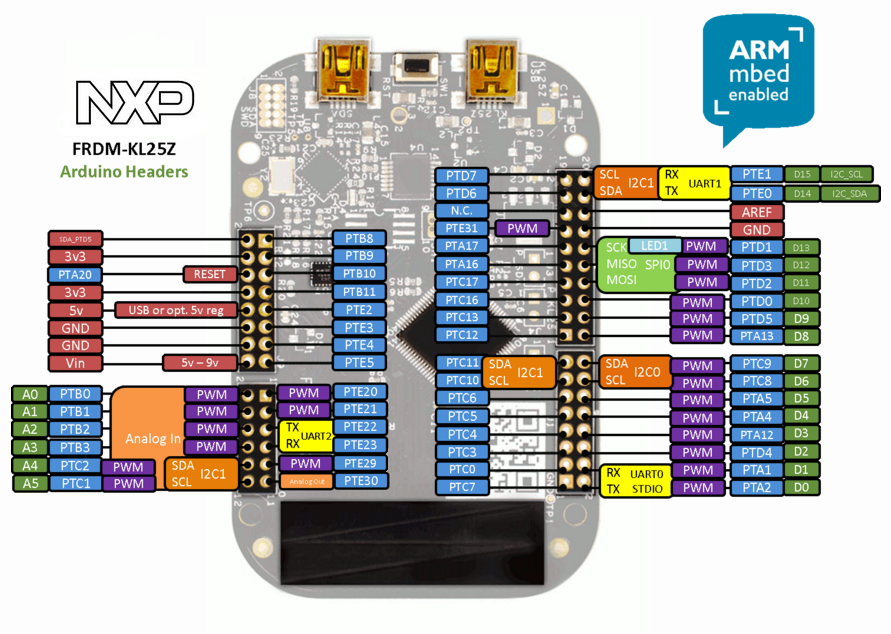

 They are working fine however. A bit of filing where the KL25Z sits and you are good.
 I thought that the VIN on the top left is only needed for the knocker part...
  Am I wrong? I'll correct it then...


 are all trademarks of VPFORUMS.