


This is my take on MJR's Pinscape expansion boards. Full credit to MJR for his great design and implementation.
I always like to improve things. In this previous thread I created my own version of the power output board. You will need two 16 output power boards to get the same 32 outputs as MJR's original power board.
After success with the power output board, I turned my attention of the controller board. I wanted to use the same pluggable screw connectors but that lead to some other compromises in space and I had to remove the four ULN2064B output drivers for RGB flashers. However I was able to make room for a Teensy and associated circuitry to drive serializable LEDs. This seems like a good compromise because most people will only want one or the other, and the hot new thing is to use serialized LEDs.
Here is a list of the improvements I made to the controller board:
- Addition of pluggable screw terminals for most inputs and outputs. The only things left with normal pin headers are the TSOP38238 and the expansion header. There are 74 terminals in all, including:
- 5V logic input and 3.3V regulated output (4)
- Up to 24 input keys
- 16 LED outputs from TLC5940 (there is no convenience common anode output and this can be wired in separately)
- 6 terminals for Plunger (+5V can be taken from the 5V logic input)
- 4 terminals for optional Plunger calibration
- Power input 5V for TV outputs and buffered outputs (2)
- 6 terminals for TV power switch and IR
- Separate power input (12V-45V) and outputs for knocker (4)
- Added LEDs on all power inputs (logic 5V, power 5V, and +V for knocker)
- Added shrouded sockets for headers to power output and chime (timed output) boards
- Added fuse, monitor LED, and optional diode for knocker output. The power for the knocker is not restricted to 12V and does not share ground with the 5V power input (unless explicitly tied together by user. All knocker output traces are 66 mils or wider.
- The original schematic makes reference to a Knocker BYPASS resistor R48 but it is not implemented. I added one to my circuit.
- Added Teensy and up to 8 addressable LED outputs. The Teensy support is separate from the Pinscape except that it shares the same 5V logic and 5V power input used for the TV etc. This board obveiates the need for a Teensy OctoWS8211 adapter board.
- Manually laid out board using only 45 degree paths and minimized number of vias for cleaner, more professional look. All 5V and 3.3V power lines are 24 mils and all signals are either 16 or 12 mils.
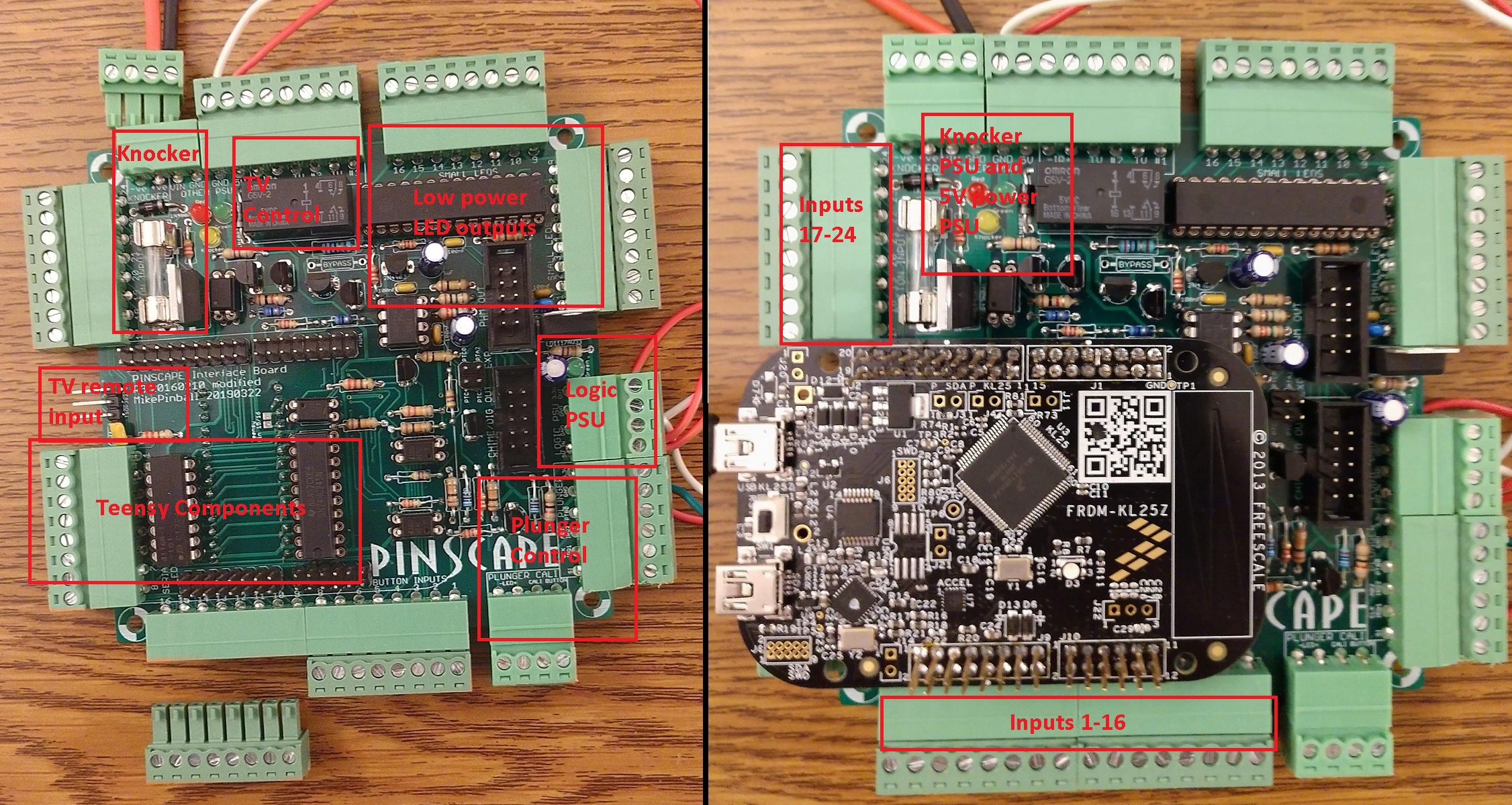
The annotated picture below shows a fully populated board without and with the KL25Z plugged in. Some pluggable screw headers are unplugged to show what they look like.
The picture below shows the controller board connected to a power output board.

The picture below shows the underneath of the controller board where the Teensy plugs into.

Edit 9/11/19: Fixed minor typo.
Edited by MikePinball, 23 May 2020 - 06:00 PM.


 Contributor


 are all trademarks of VPFORUMS.