


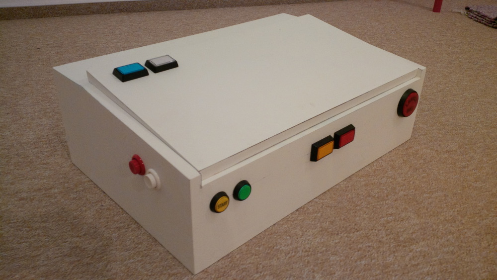
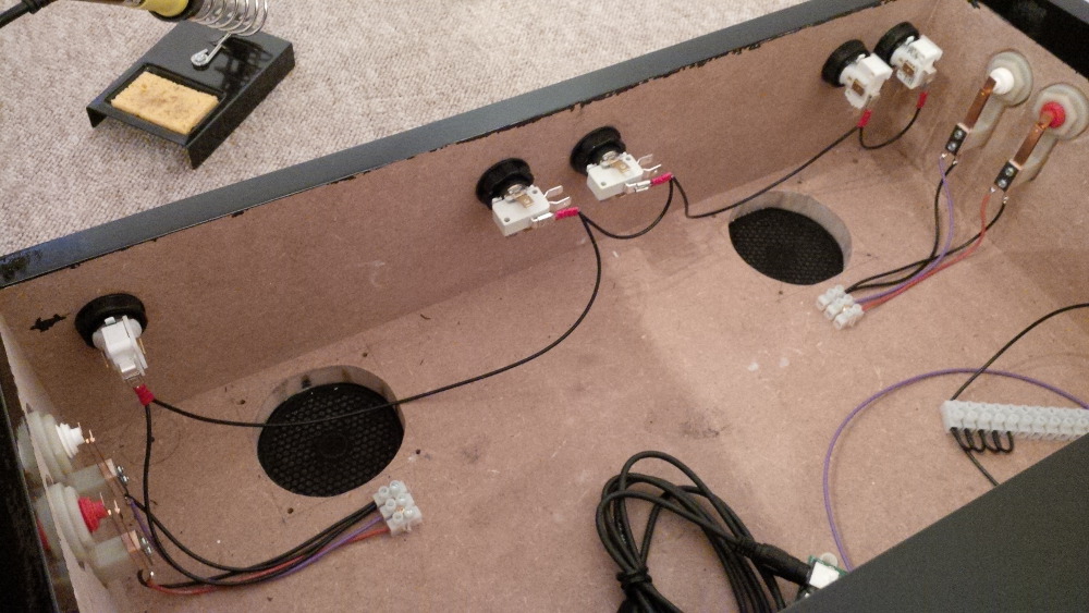
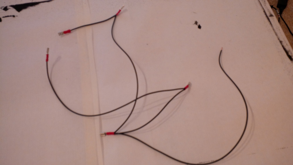
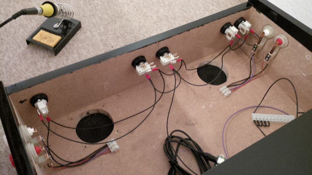
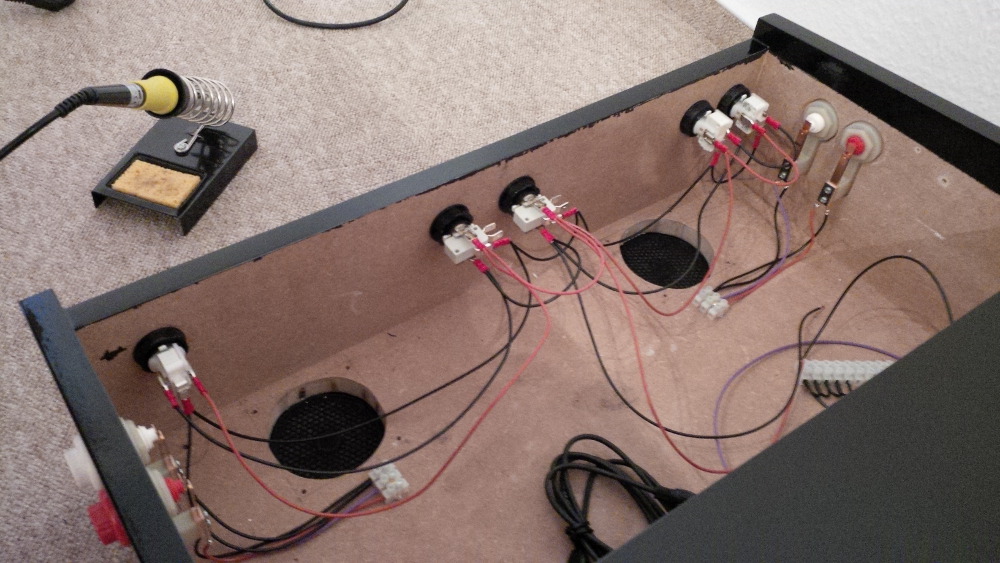
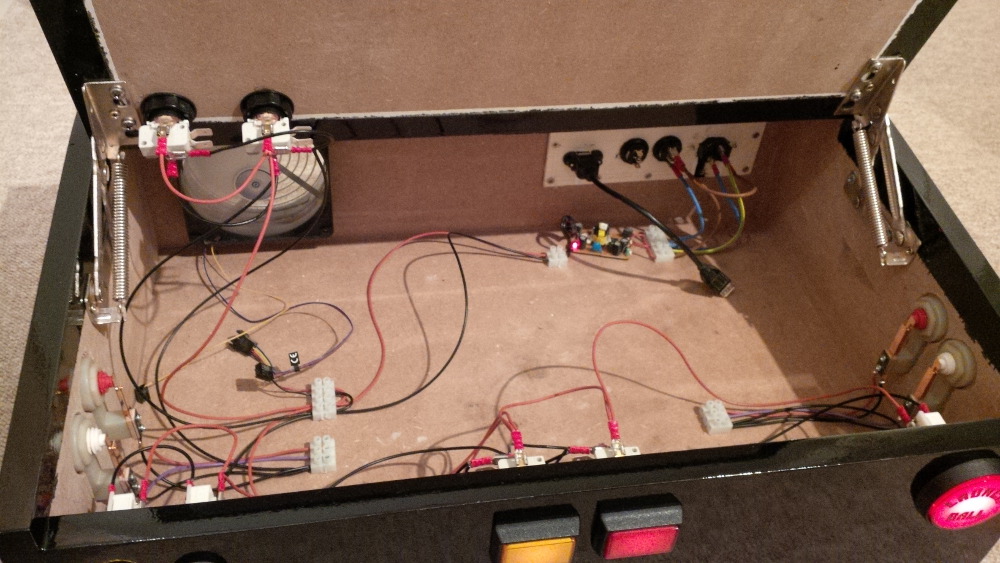
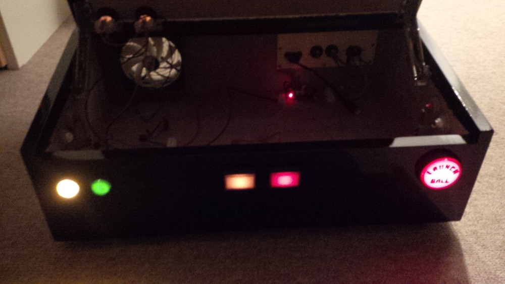
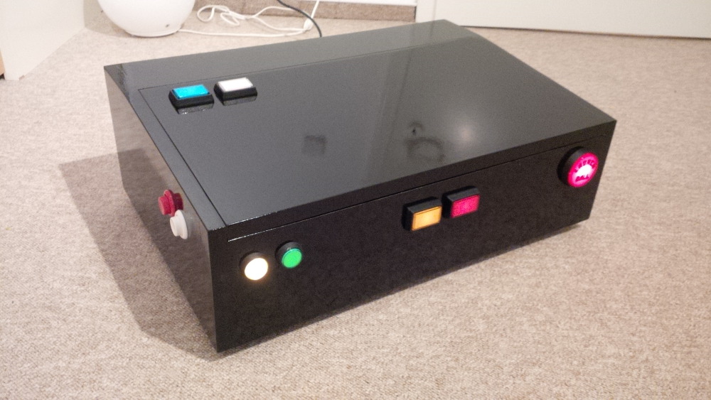
As intro and to allow a fast navigation I'll provide some pics of my current status and a list of contents here within the opening post.
Current status
List of chapters
- Dreaming
- How to get inexpensive progress?
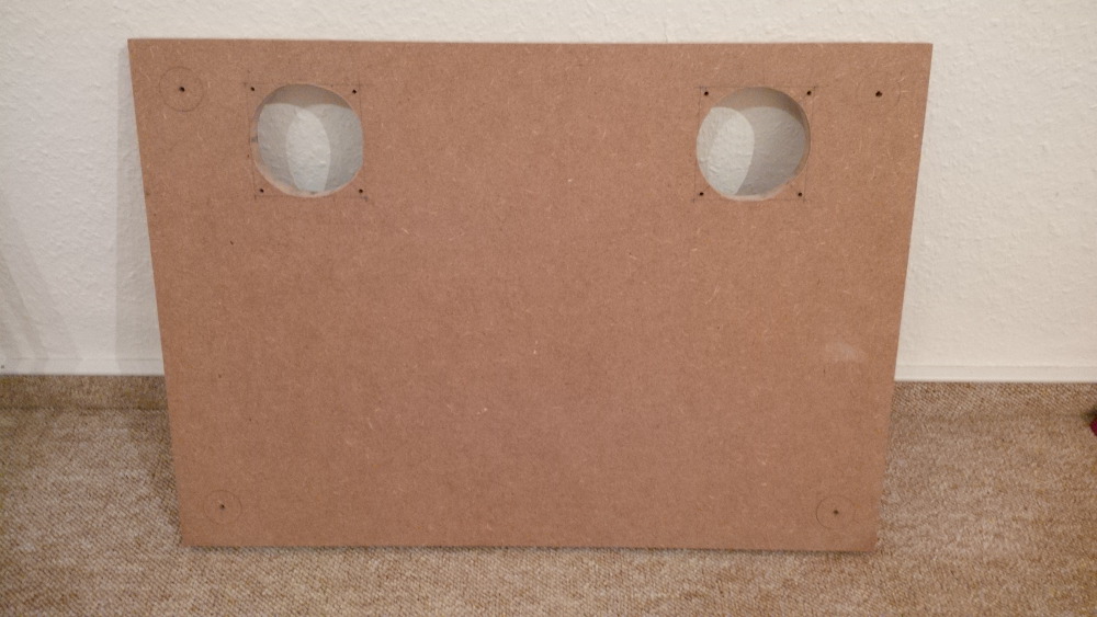
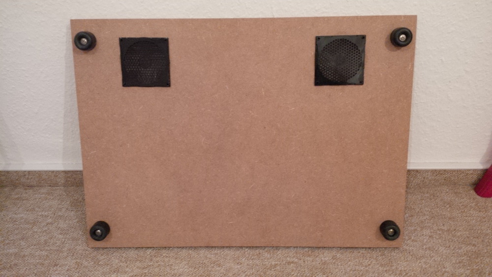
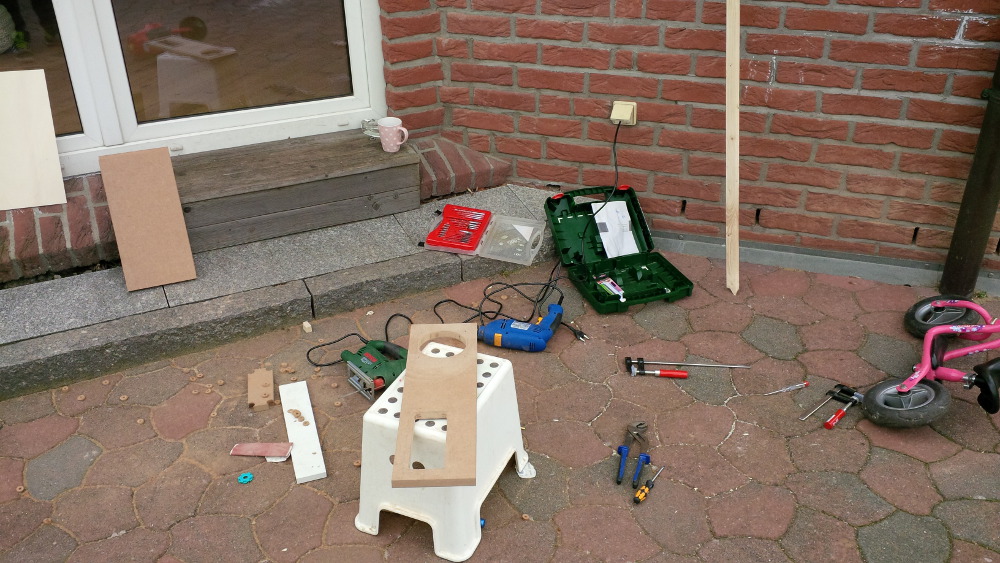
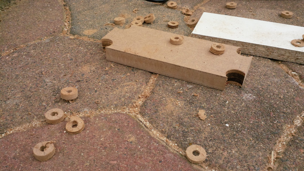
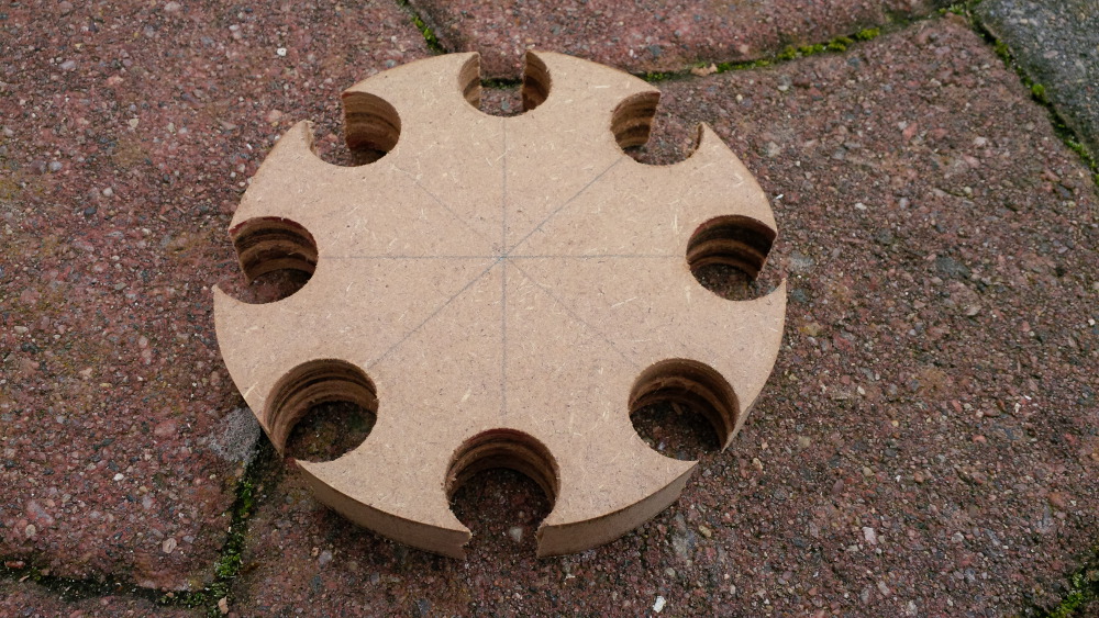
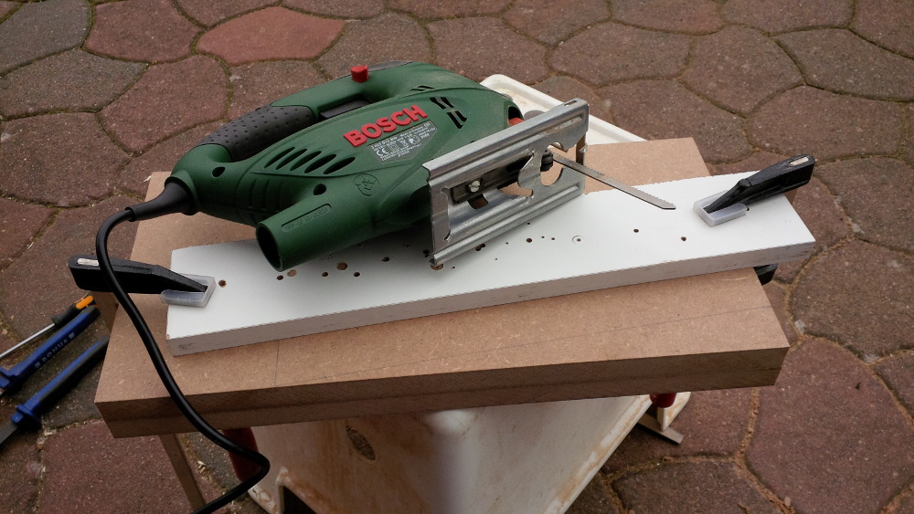
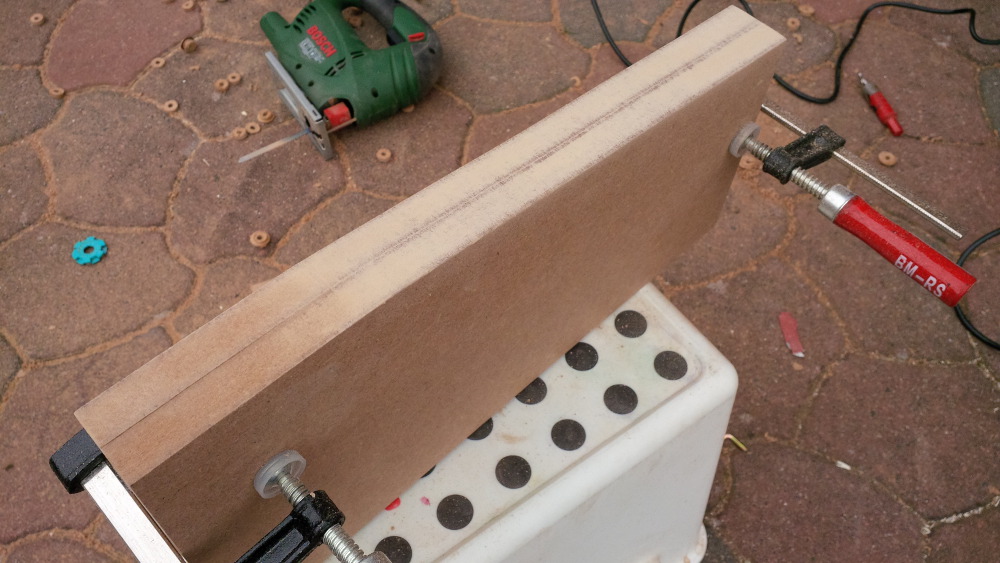
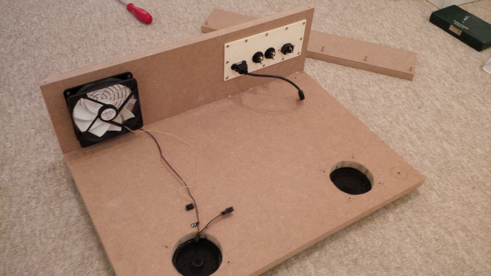
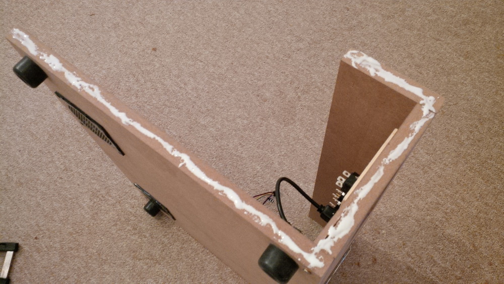
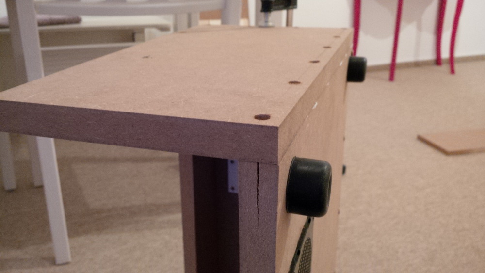
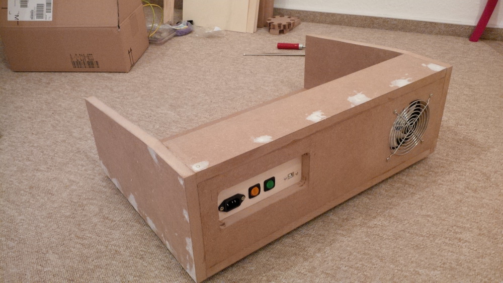
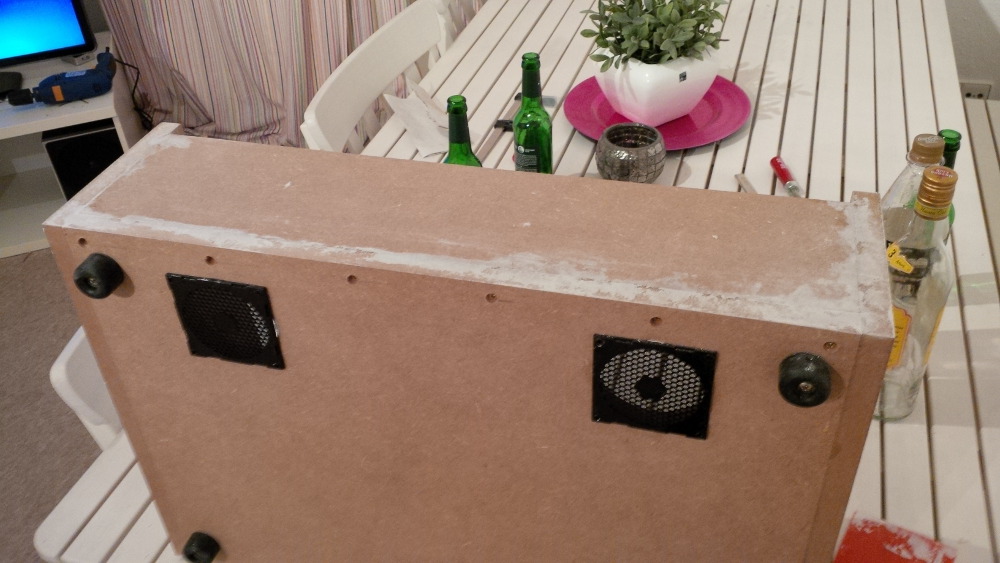
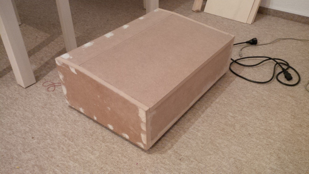
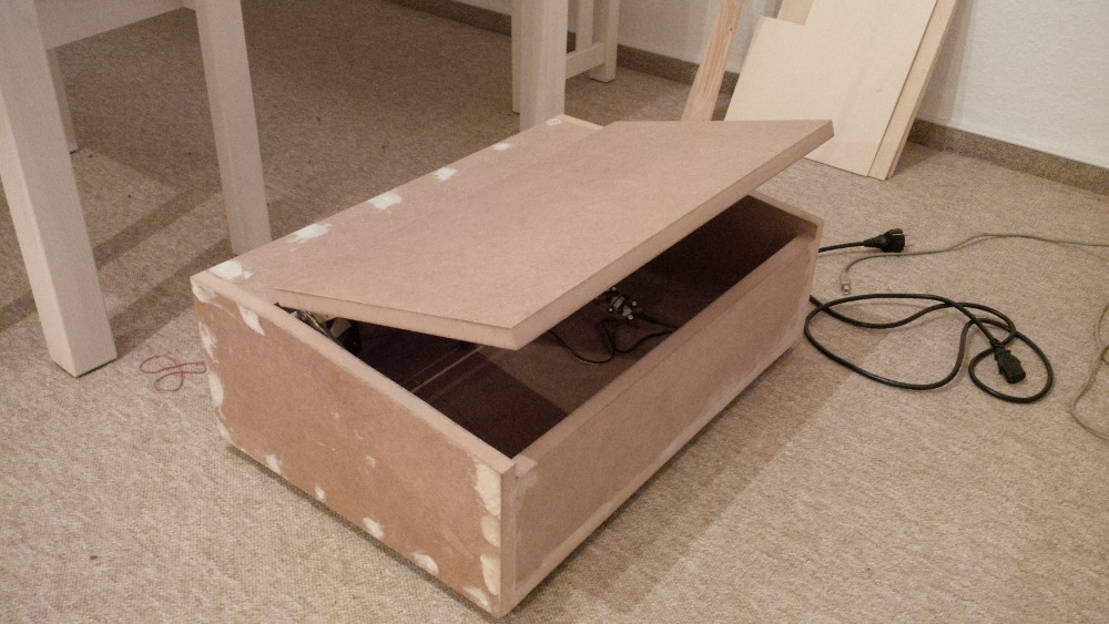
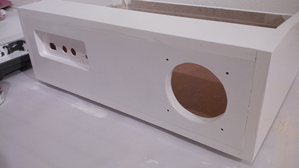
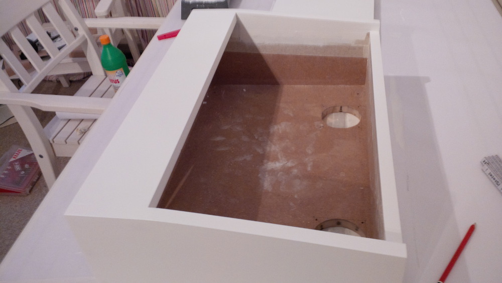
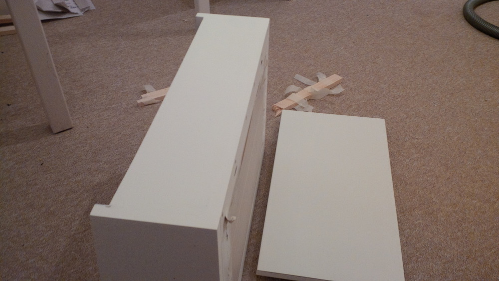
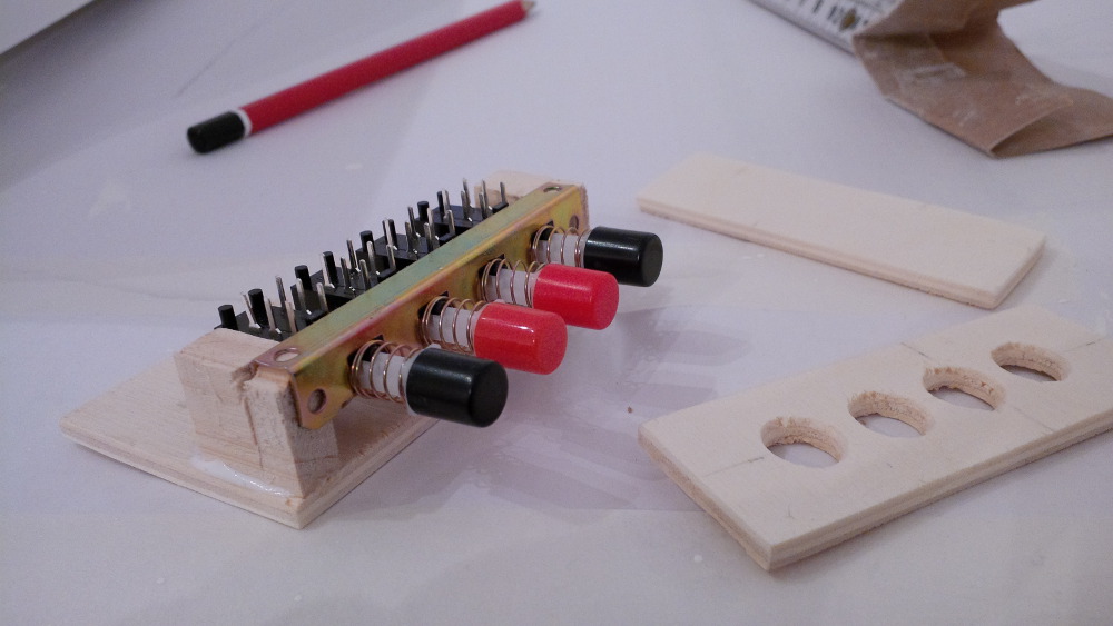
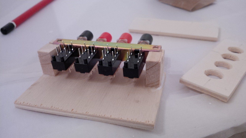
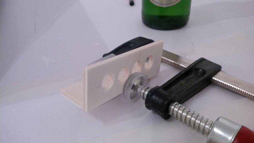
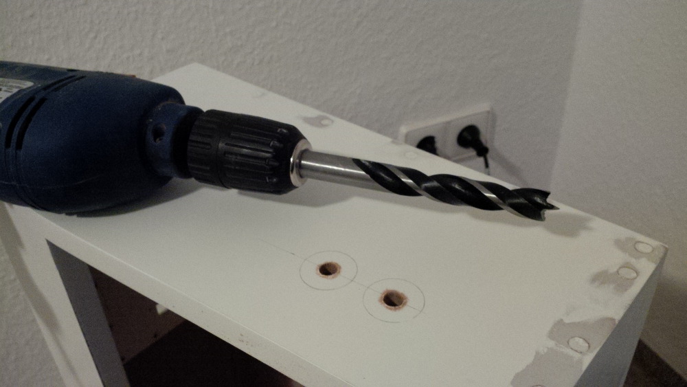
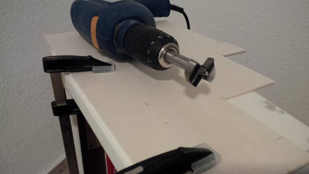
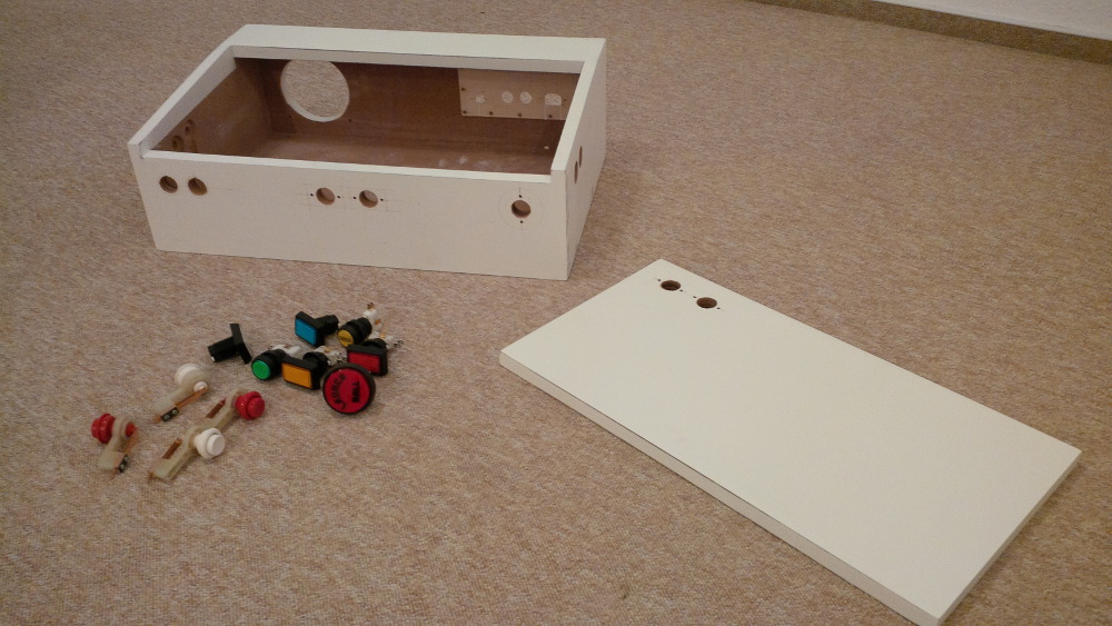
- Wood working
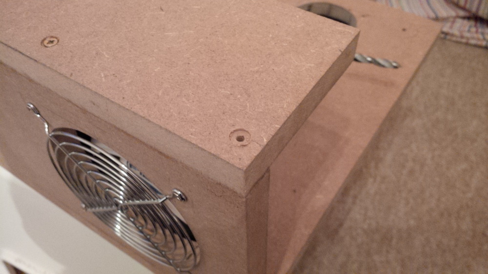
- Screws and glue
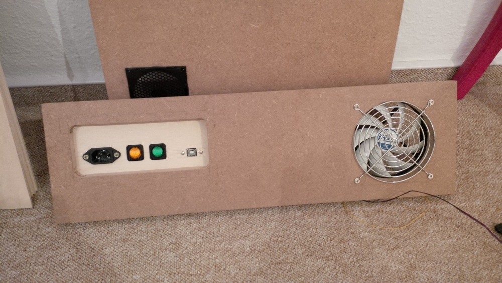
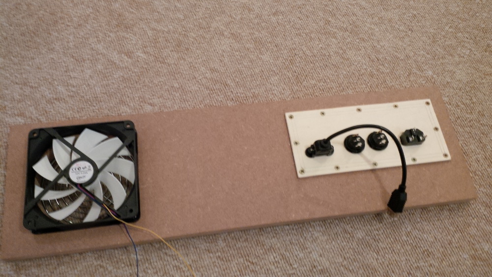
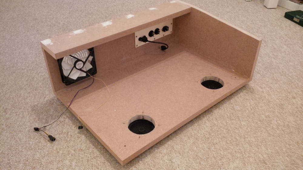
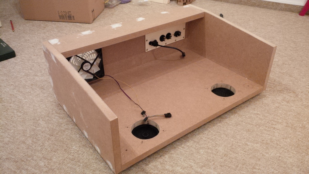
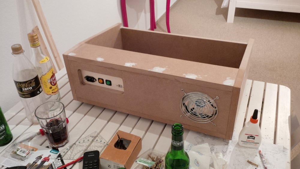
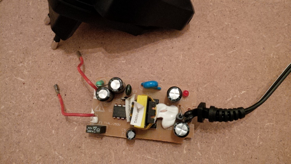
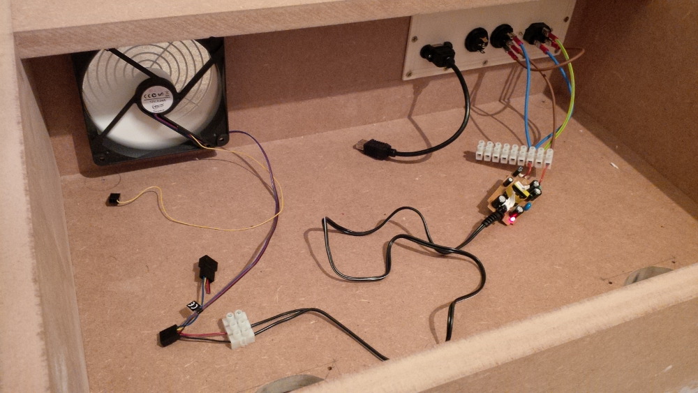
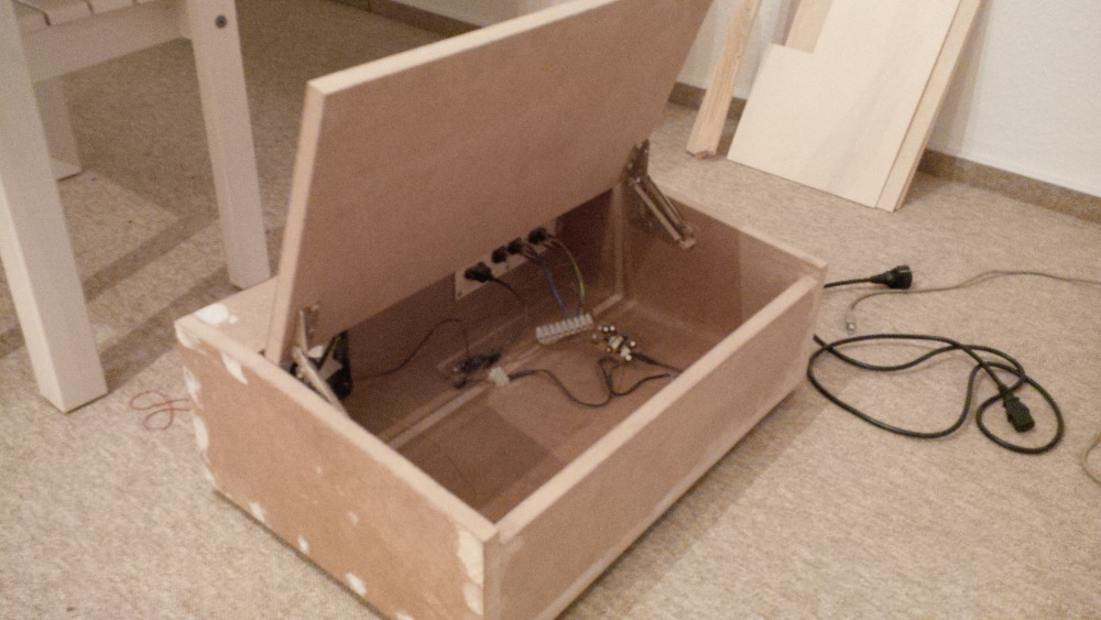
- A really small power supply
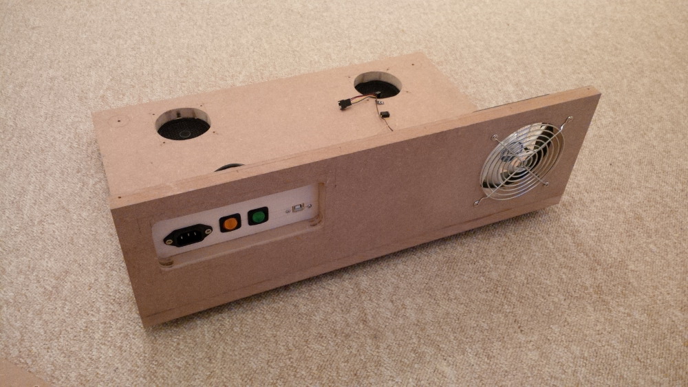
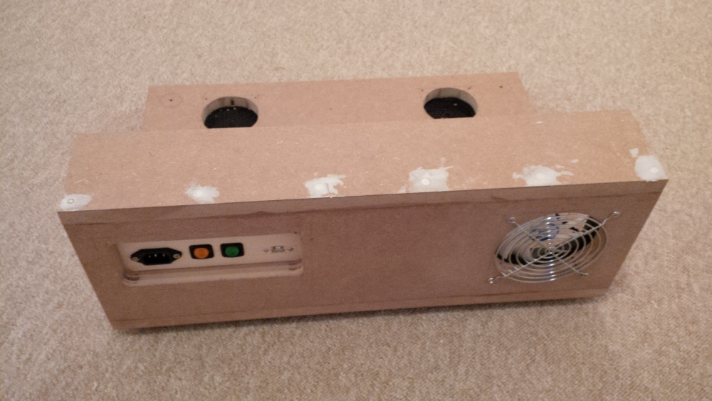
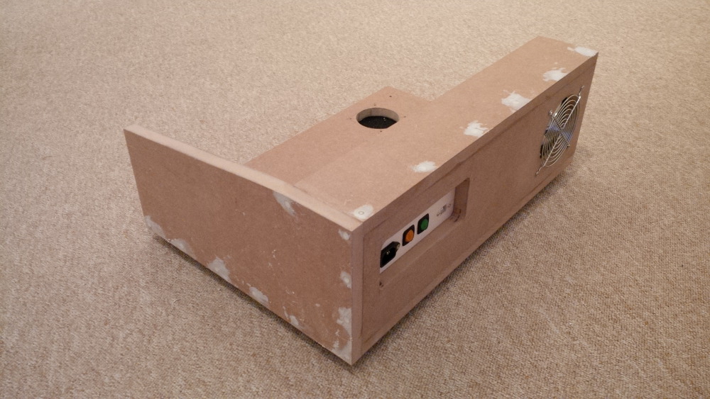
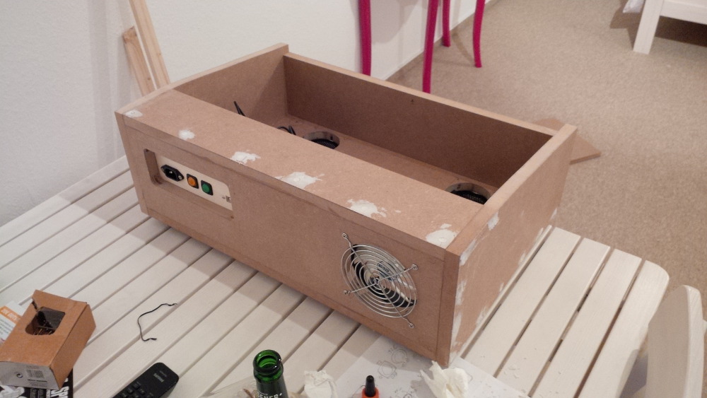
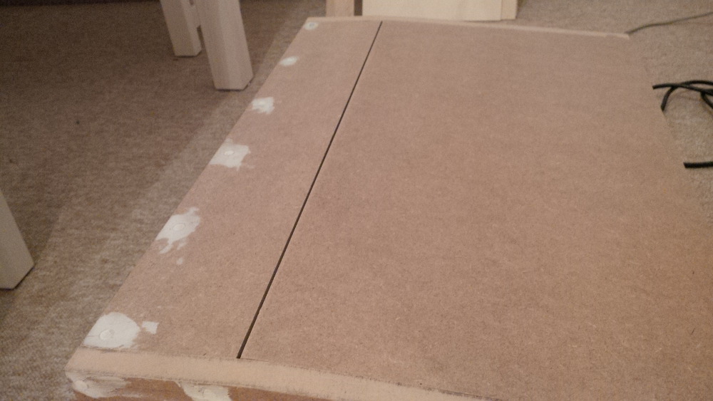
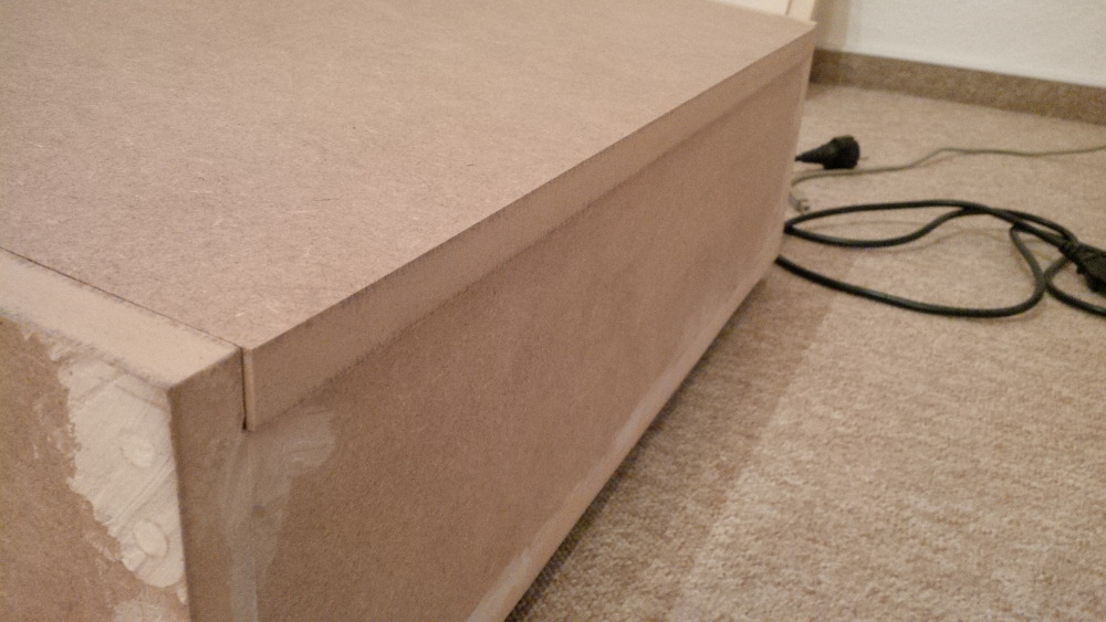
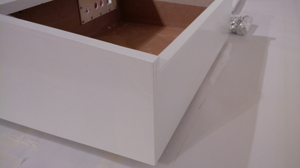
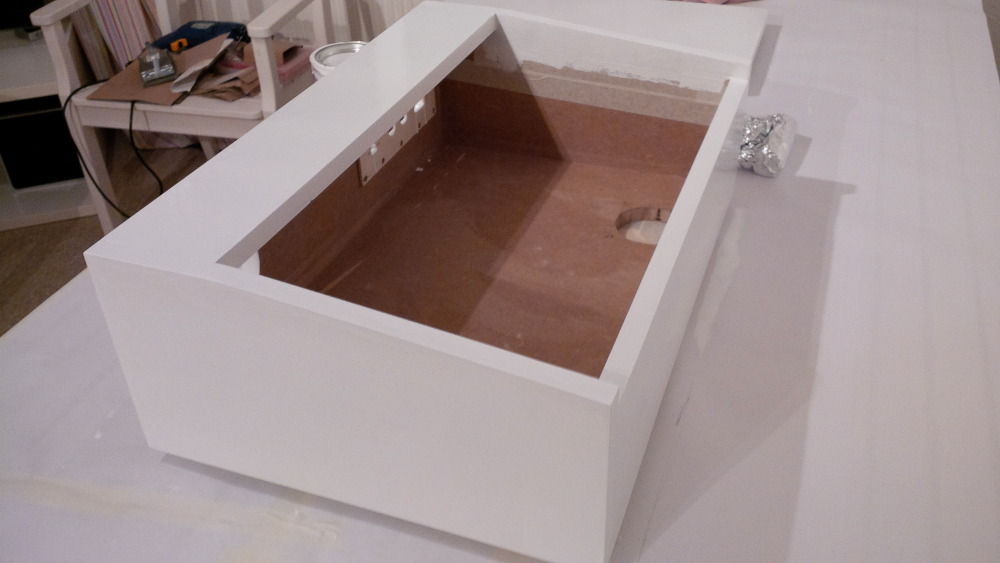
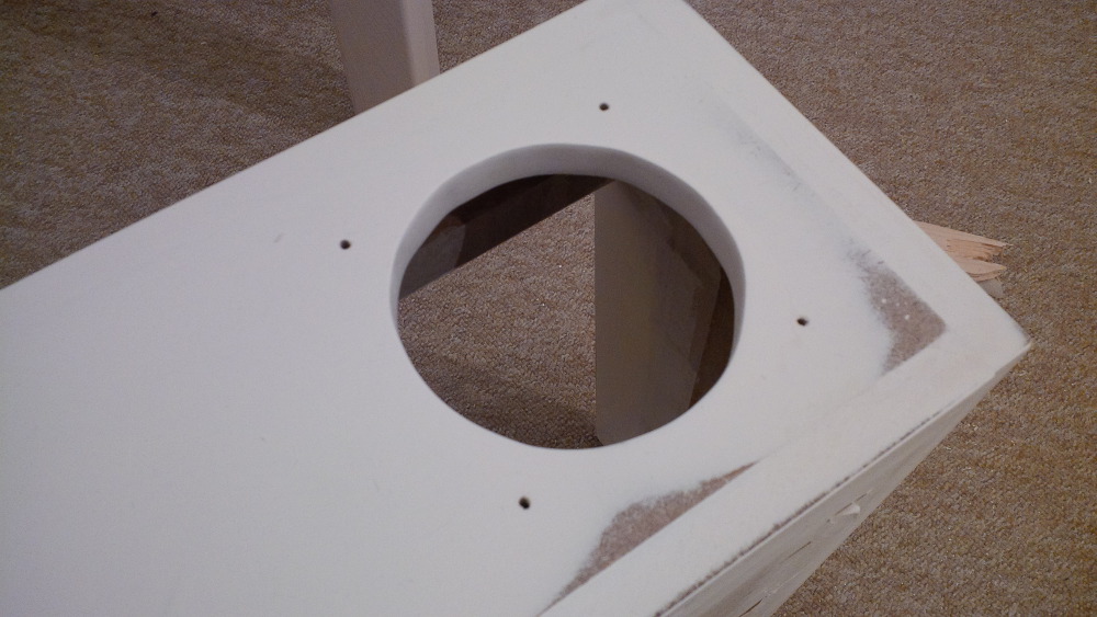
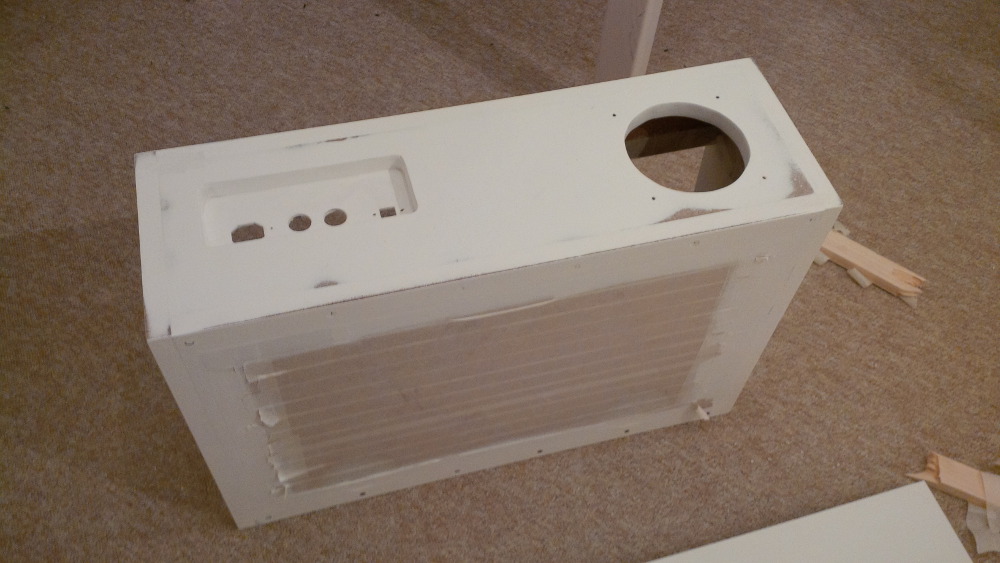
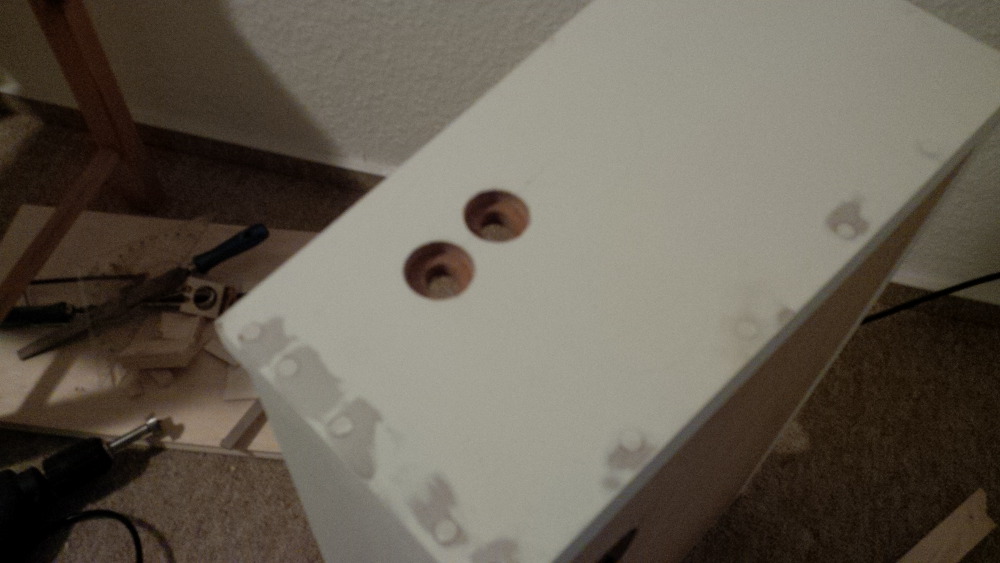
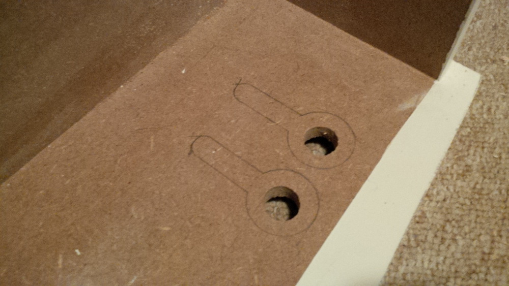
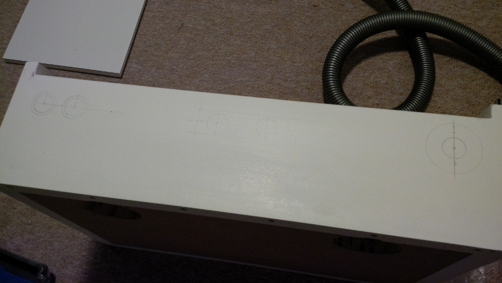
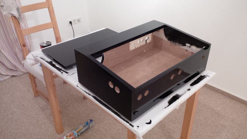
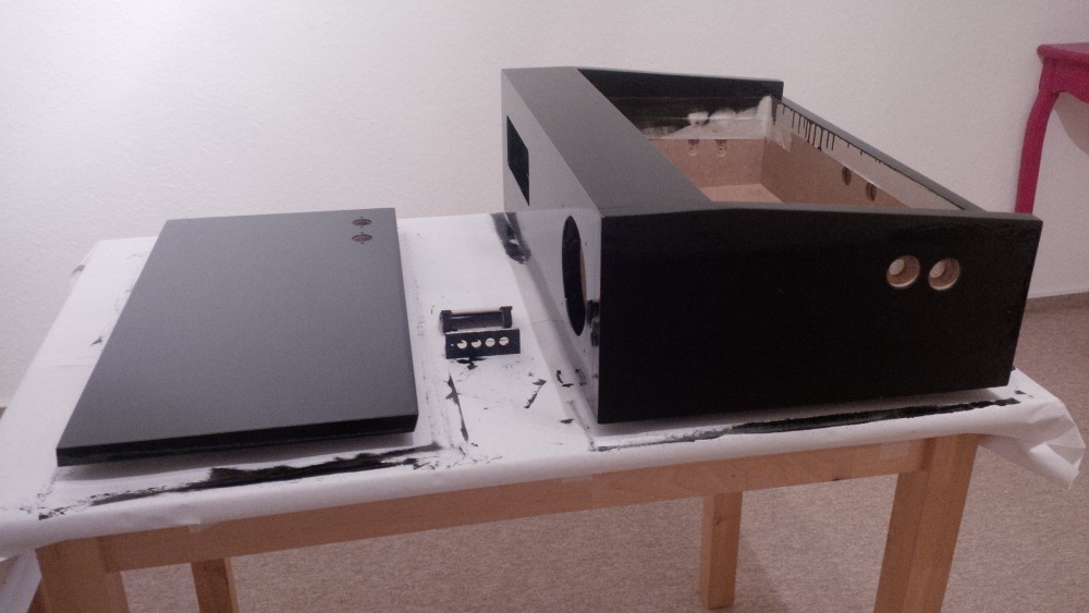
- Case top
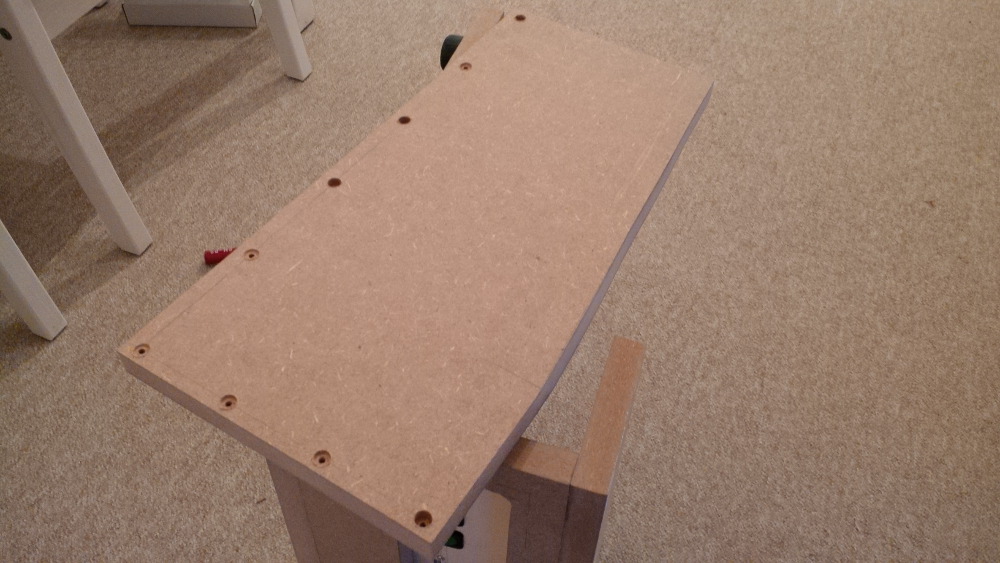
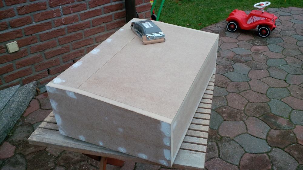
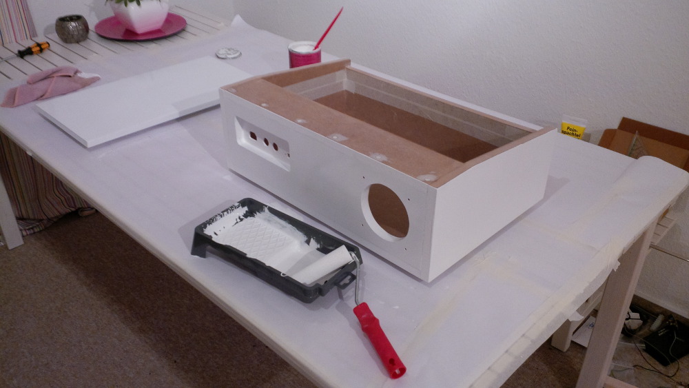
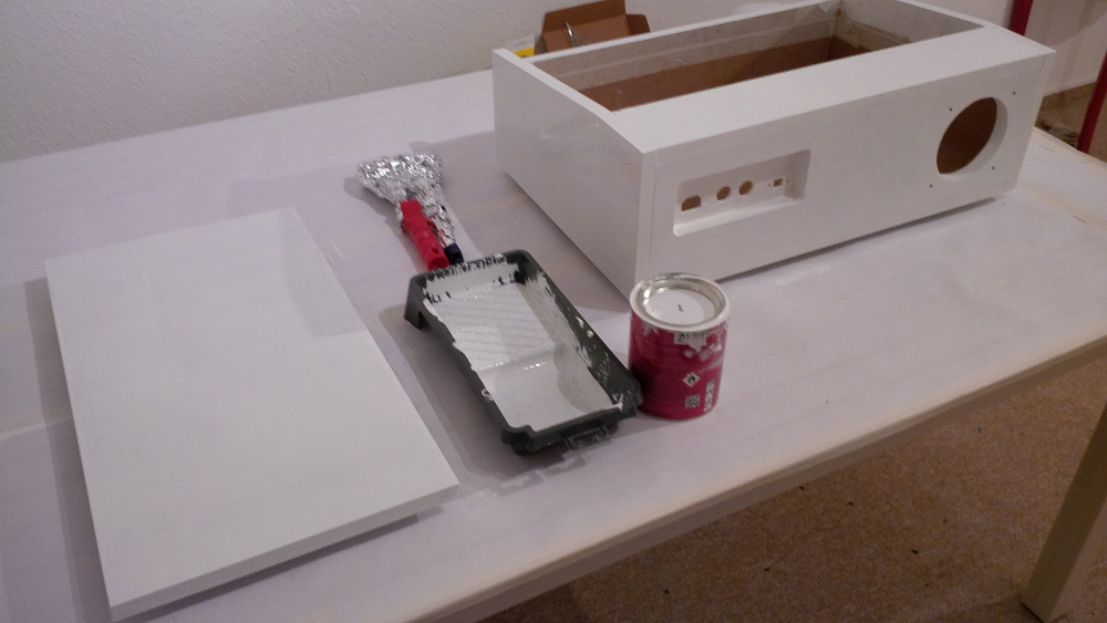
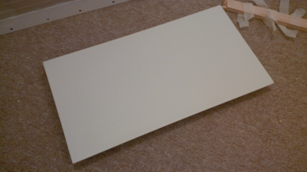
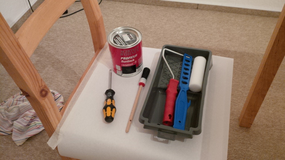
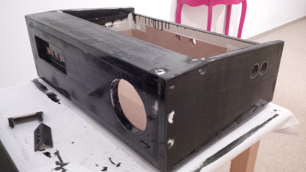
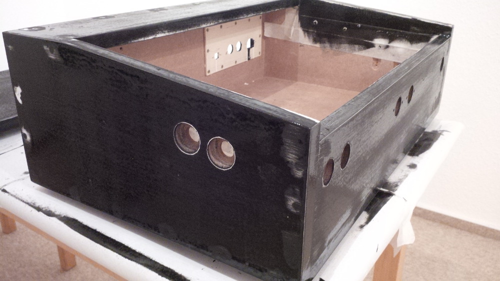
- Start painting
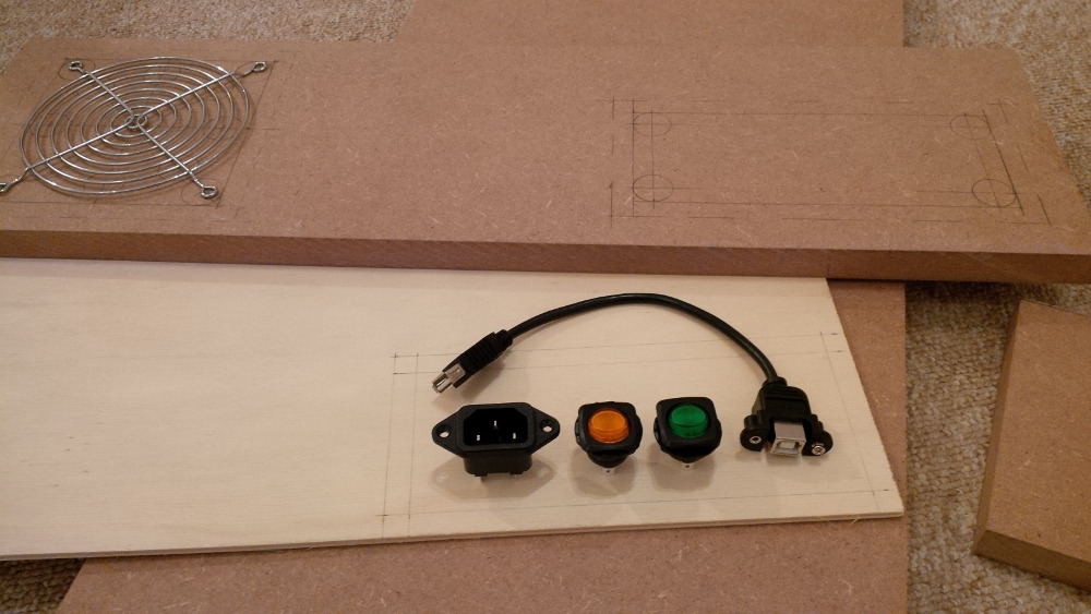
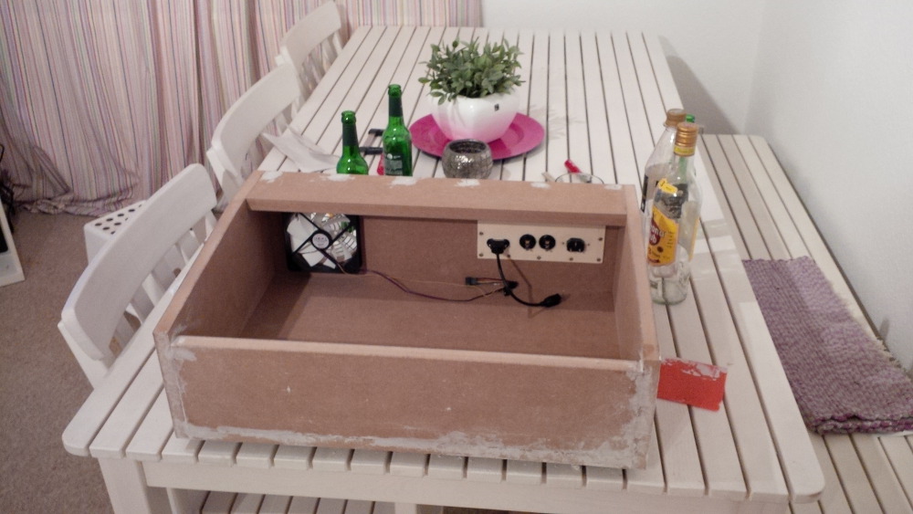
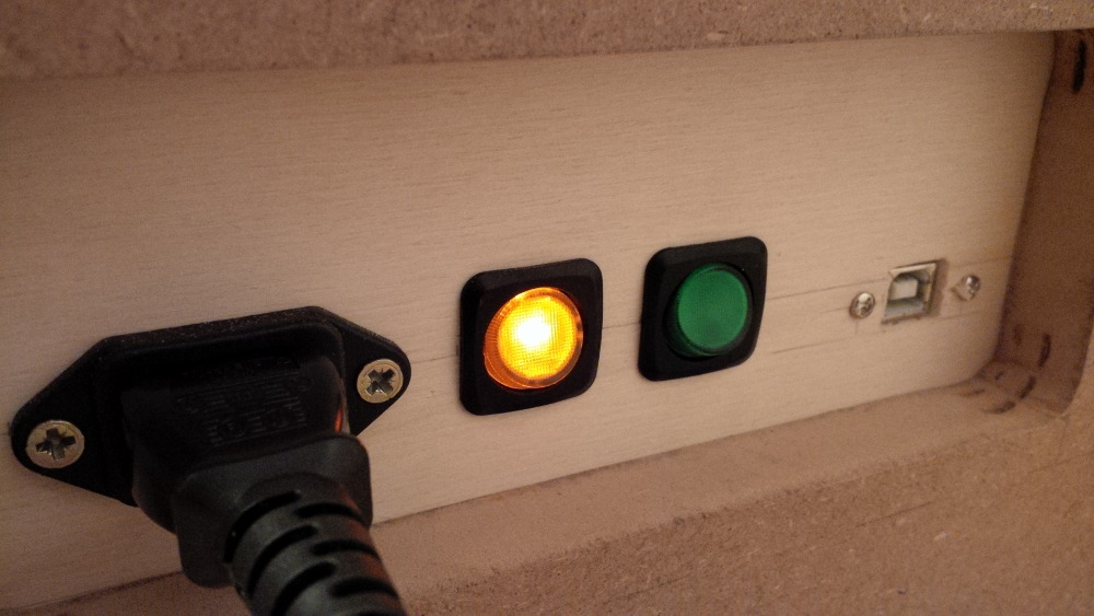
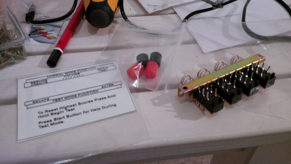
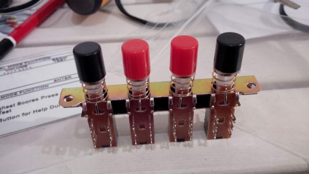
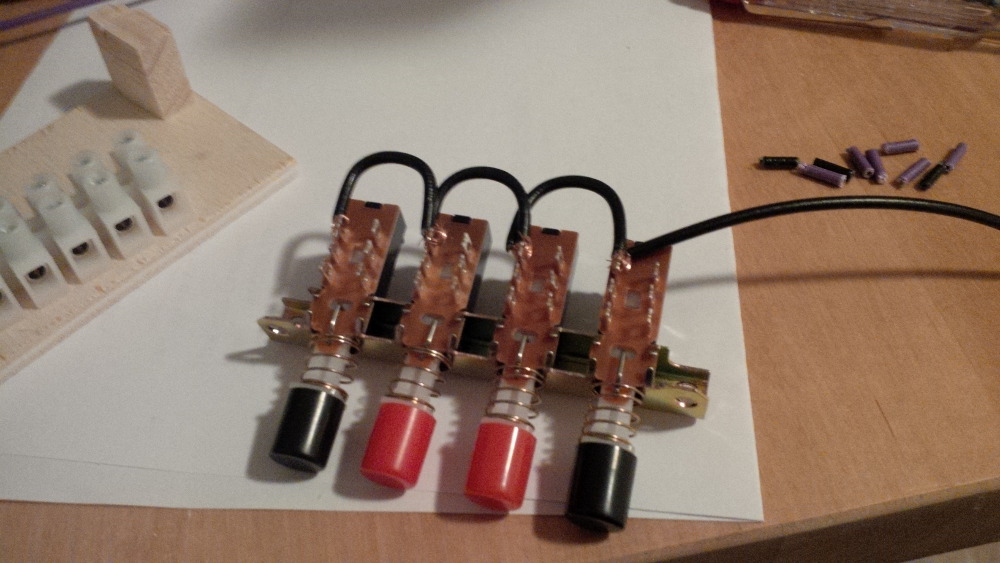
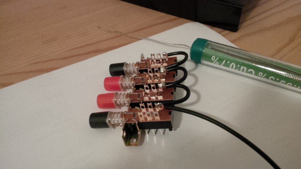
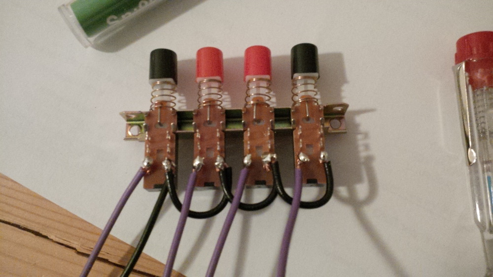
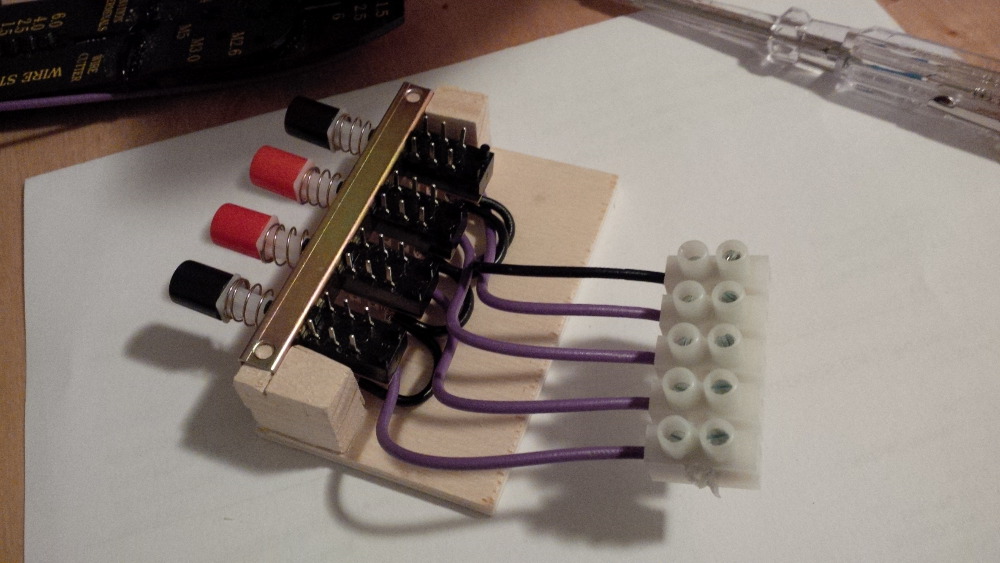
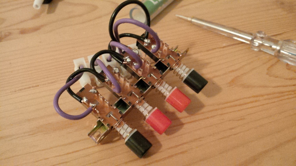
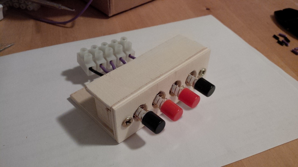
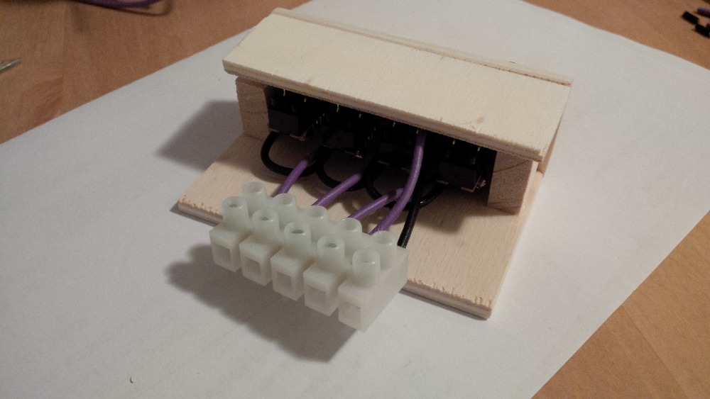
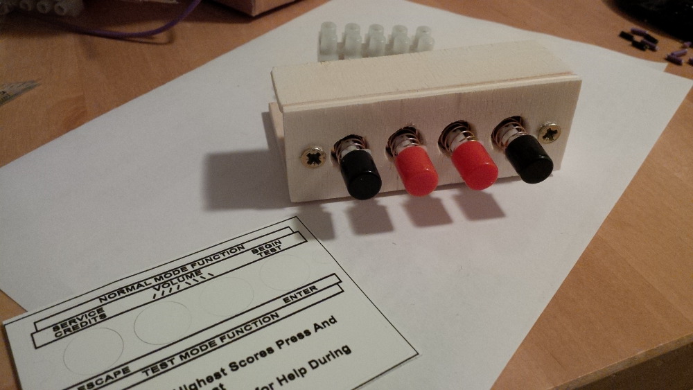
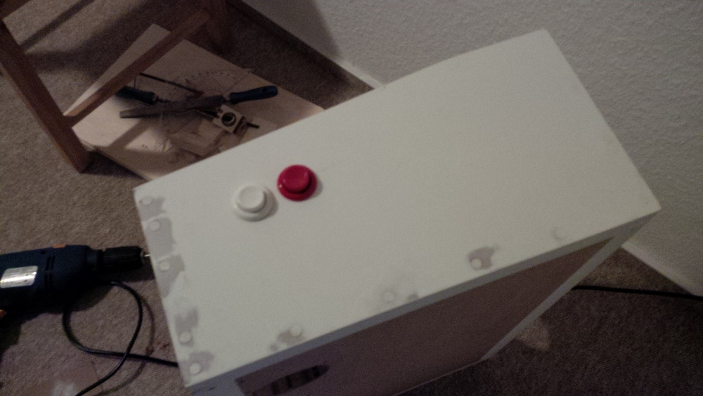
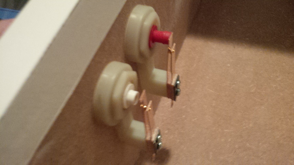
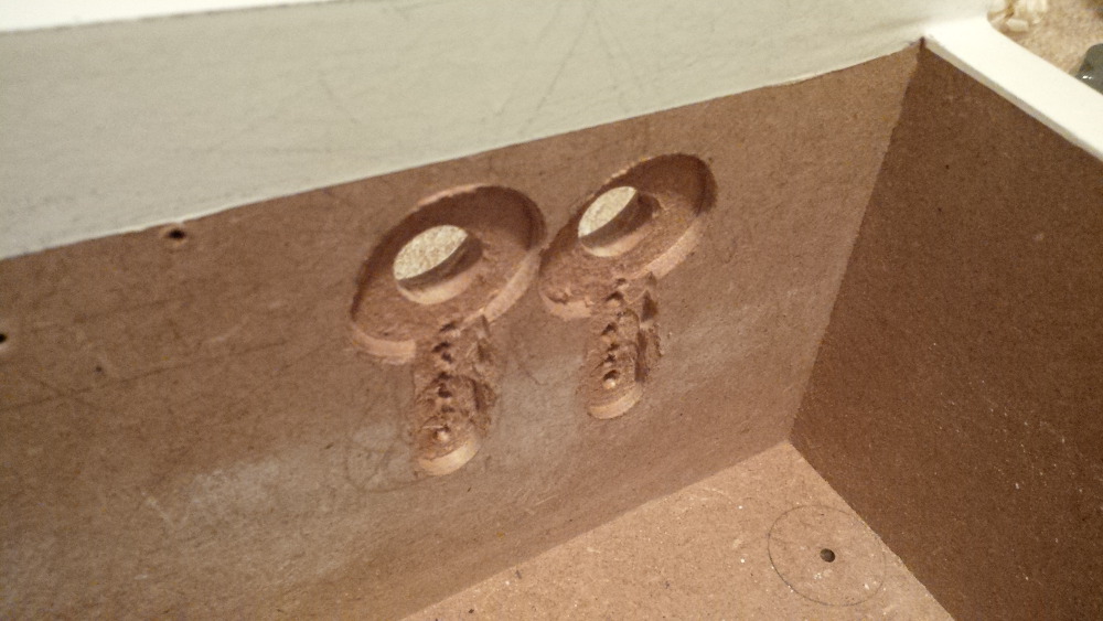
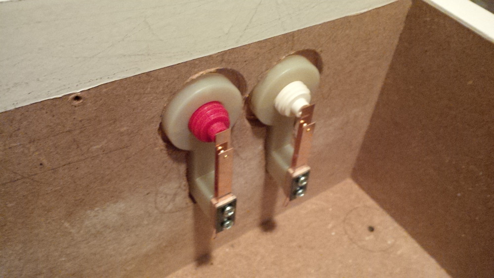
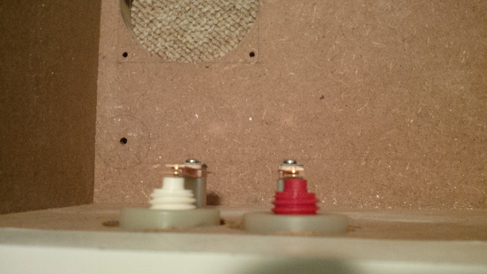
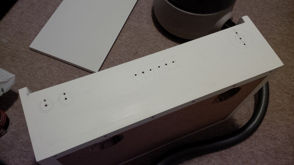
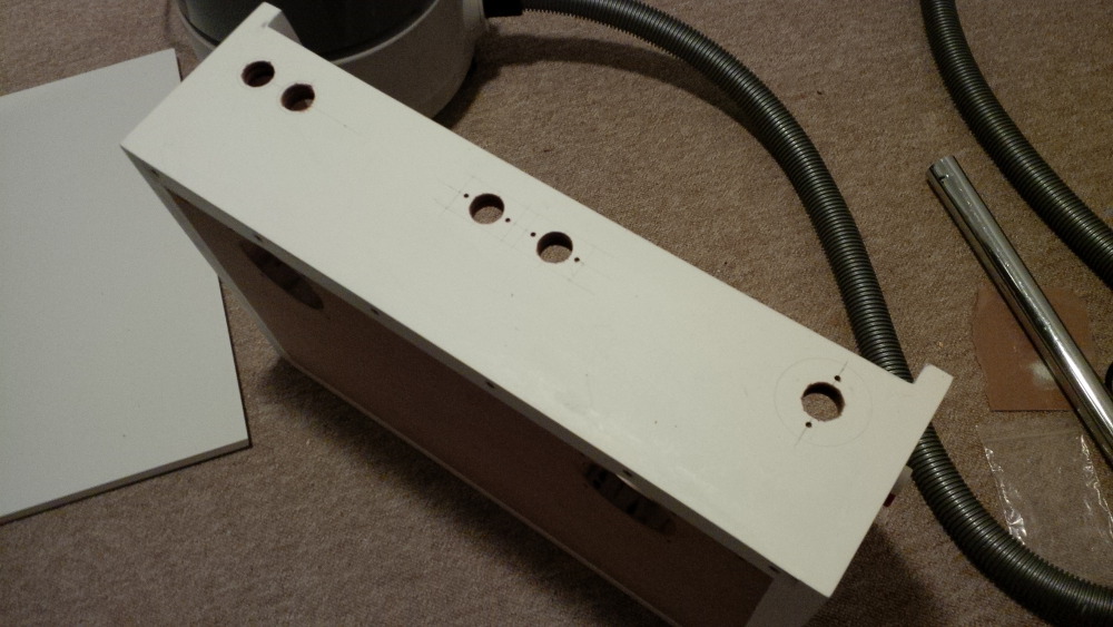
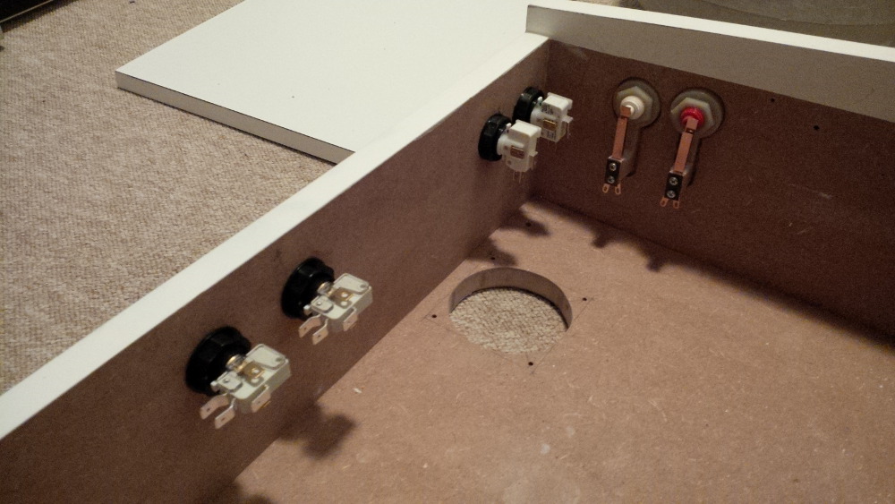
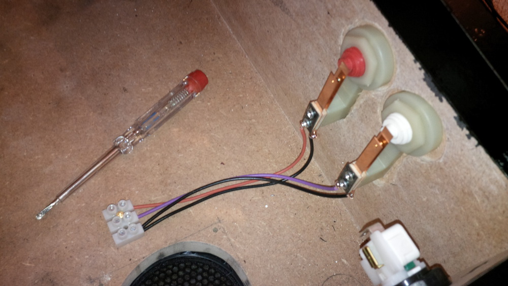
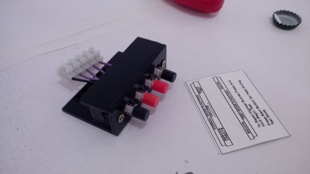
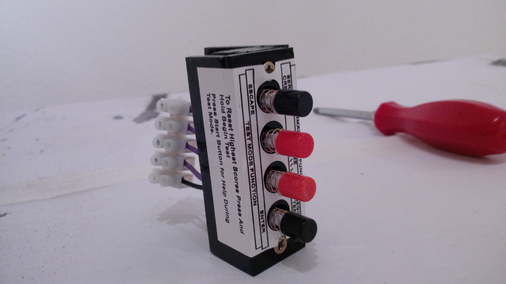
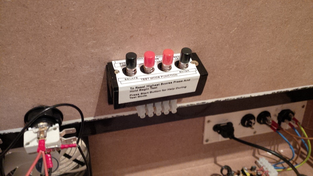
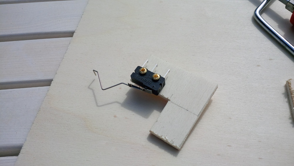
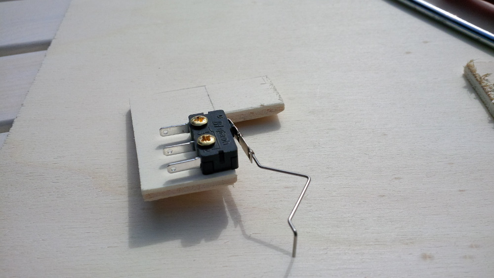
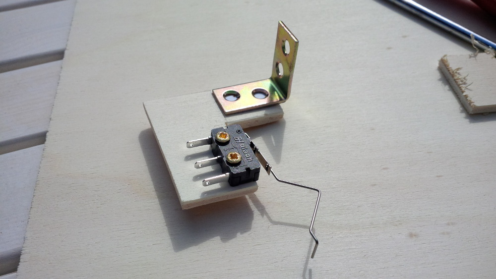
- Service buttons
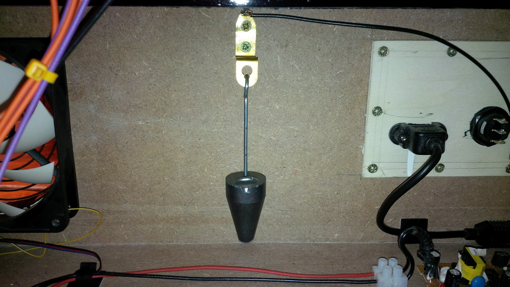
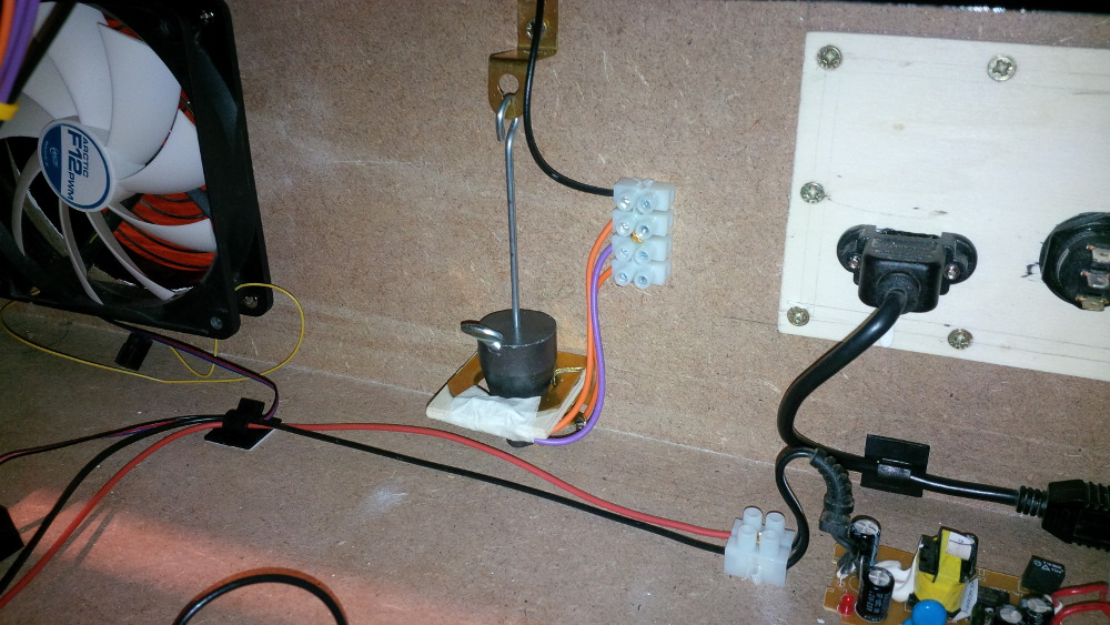
- Nudging
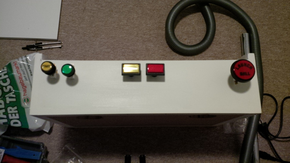
- My buttons arrived
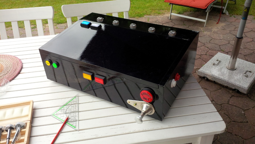
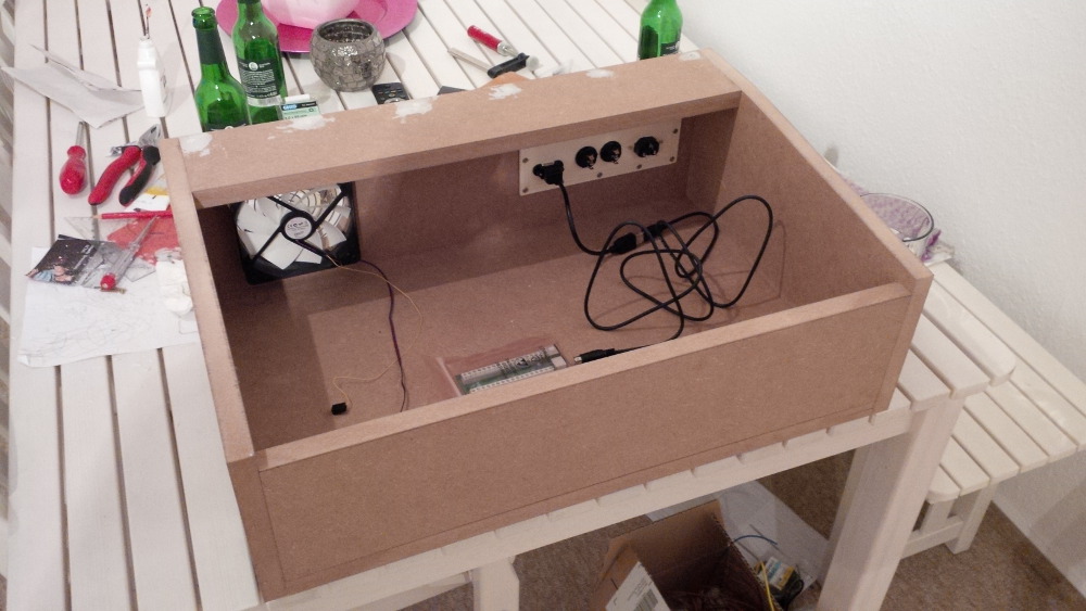
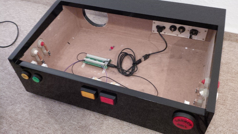
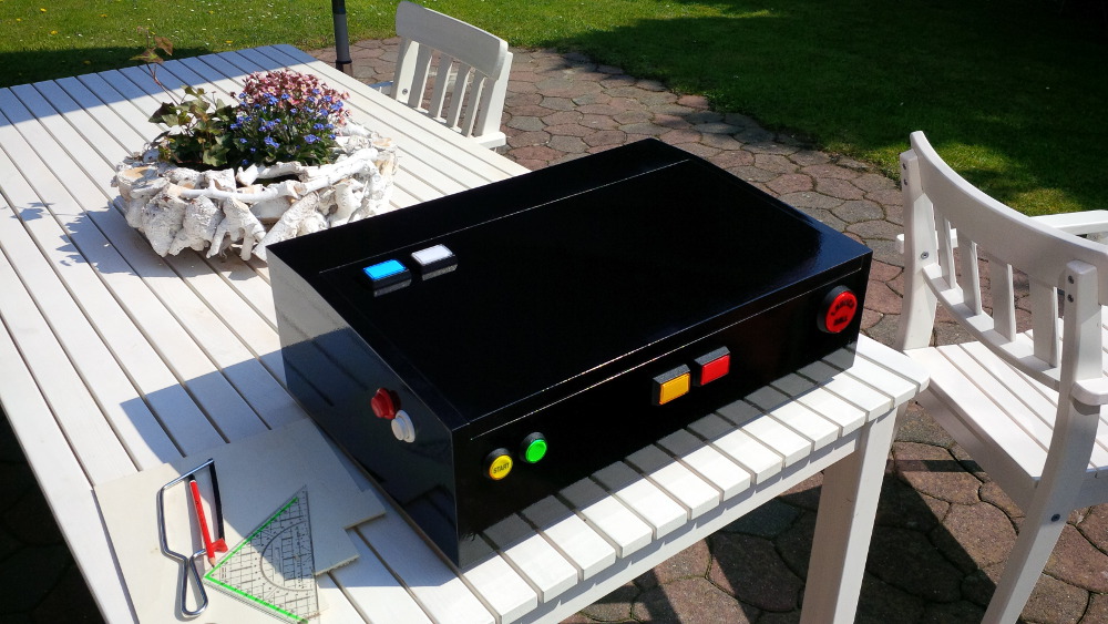
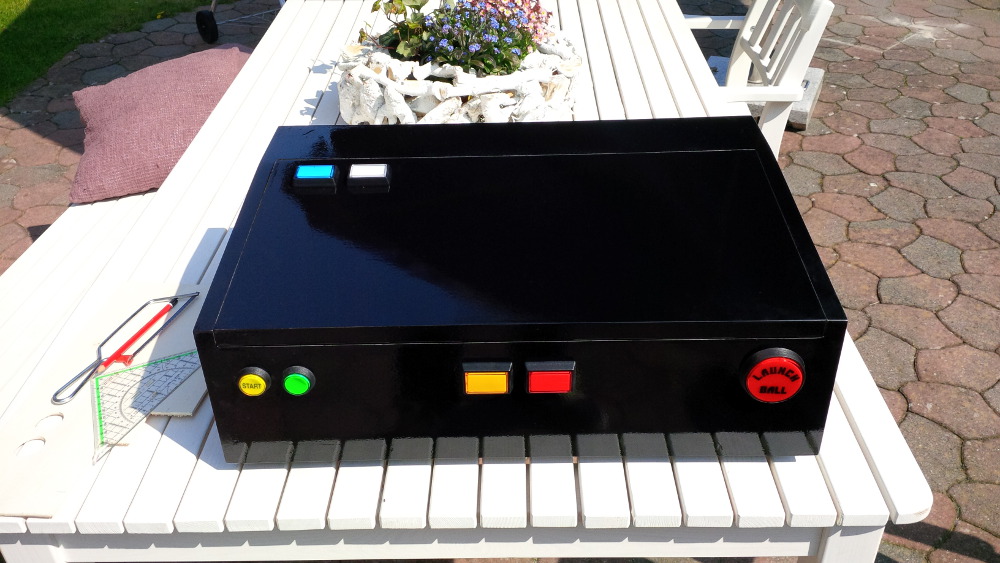
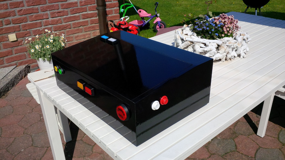
- A black box
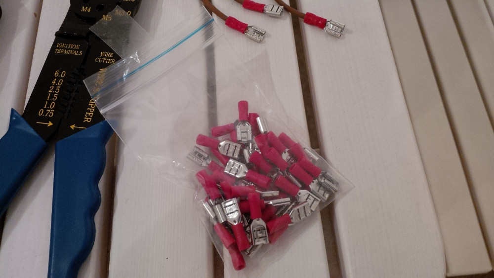
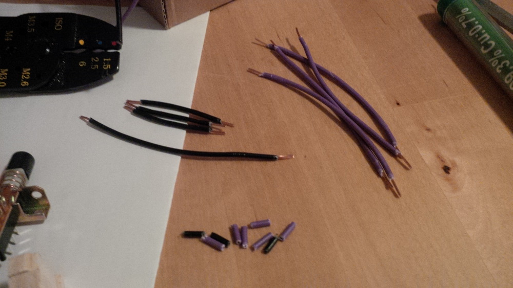
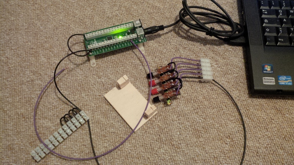
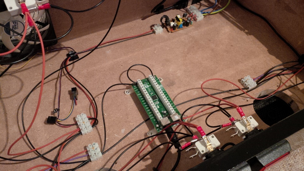
- Some wires and a first game
- Making an order and playing around
- LEDWiz
- Resistors and some heat sinks
- Crocheting
- Flasher
- First force feedback
- Plunger
- A disappointing bulb replacement
- Next level
- A clean up
- New parts arrived, an important cab builder tool
- Some cabinet makeup
- A shaker - "let's get ready to rumble"
- A relay board for more fancy toys
- A gear motor and a bumper surprise
---
Soooo, while I'am waiting for a package with some new toys it's time to start my build thread. I hope to support you with my experiences as a complete newbie in virtual pinball, electronics and wood working ;-). Please learn from my faults.
Chapter I - Dreaming
For many years I was passionate interssted in virtual reality, big screen multitouch devices and interactive art installations. On the other hand I really love to play pinball, but unfortunately it is hard to find some pins in my city. To get an millionair to be able to buy a couple of nice pins is in a status like "work in progress", but currently I have to spend my money for living, food, a wife and my daughter instead of spending thousands of euros in pinball hardware.
On a evening after some beer I got an really good idea - what is about a virtual pinball simulation? A digital one, a big screen, force feedback and a lot of tables that would be playable. After a few minutes I found these community :-) firstly I was disapointed that somebody else had this great idea before myself, but than I got stuck in reading posts of all you guys and start dreaming in building my own virtual pinball table...
Ahhhh... hmmmm...
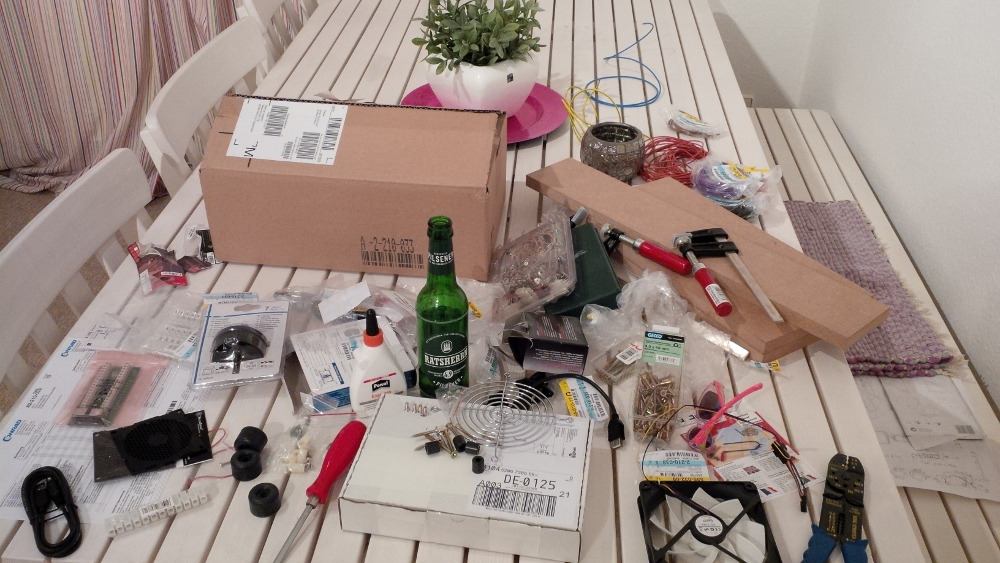
On the next days I created several shopping lists and it really hurts to realize that a virtual pin isn't cheaper than a real one :-(. For everybody that is falling in a idea like that: The costs can be splitted in the following categories:
- You need a cabinet. Yea, it's a possible option to get some wood in a local store, but than you would need collect a wide range of real pinball parts to round up your build like pinball legs, an unbelievable expensive lockdown bar, a coin door, plunger, buttons, glas, rails, and and and... In the end you would end up with something about 800 euros. Alternatively you could try to find an empty cabinet, but if you want to find one as a widebody variant than you will notice soon that there isn't a big amount of offers. To buy a pinball that is alive isn't an option for me, because a working one (or almost working one) has to keep alive.
- You need a set of gamers hardware (pc). That means a fast processor, a related mainboard, RAM, an SSD, power supply and the most expensive part: a set of modern graphic cards to keep everything running smoothly on three screens. Alternatively you could work with one fat Geforce card, but than you would have to order a real DMD (means dot matrix display) and related controls and this is definetly not a cheaper (but probably nicer) option.
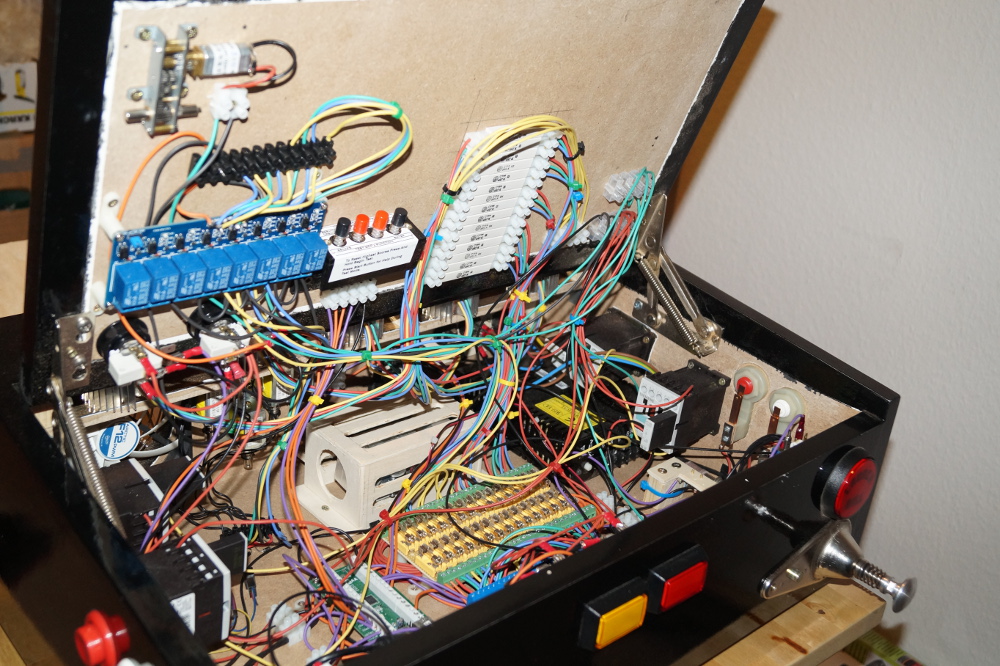
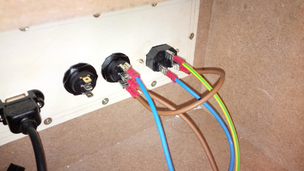
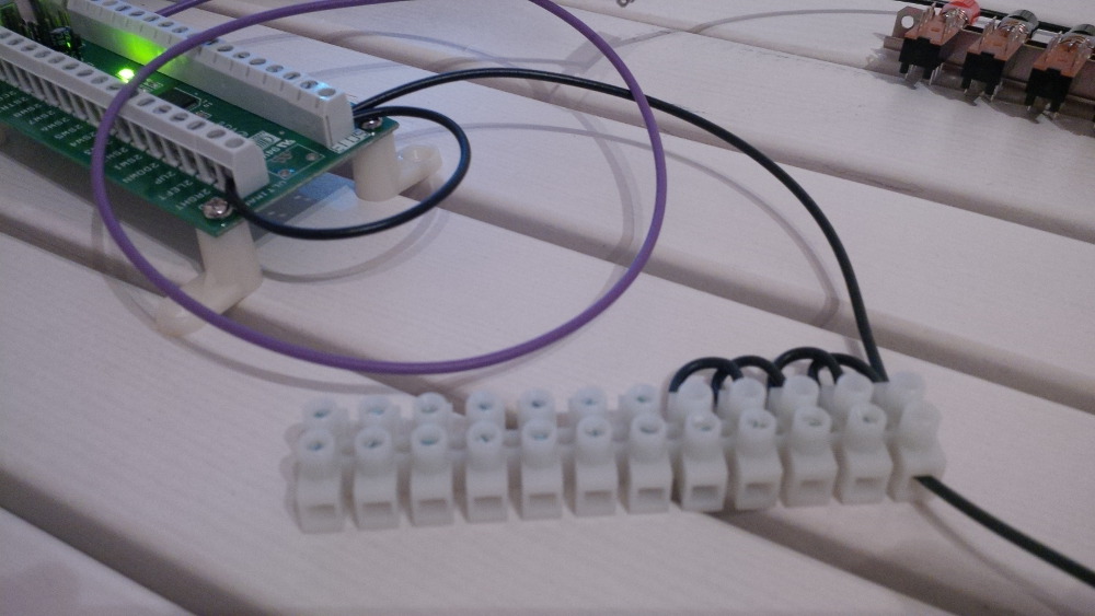
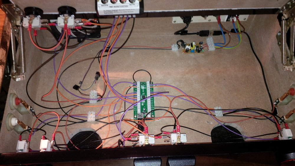
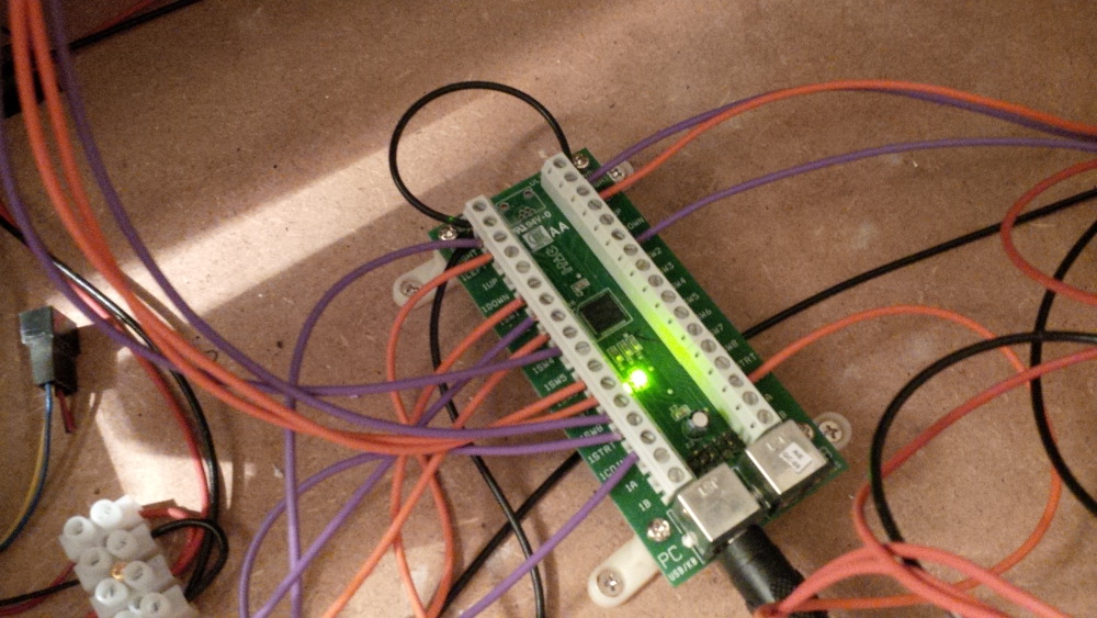
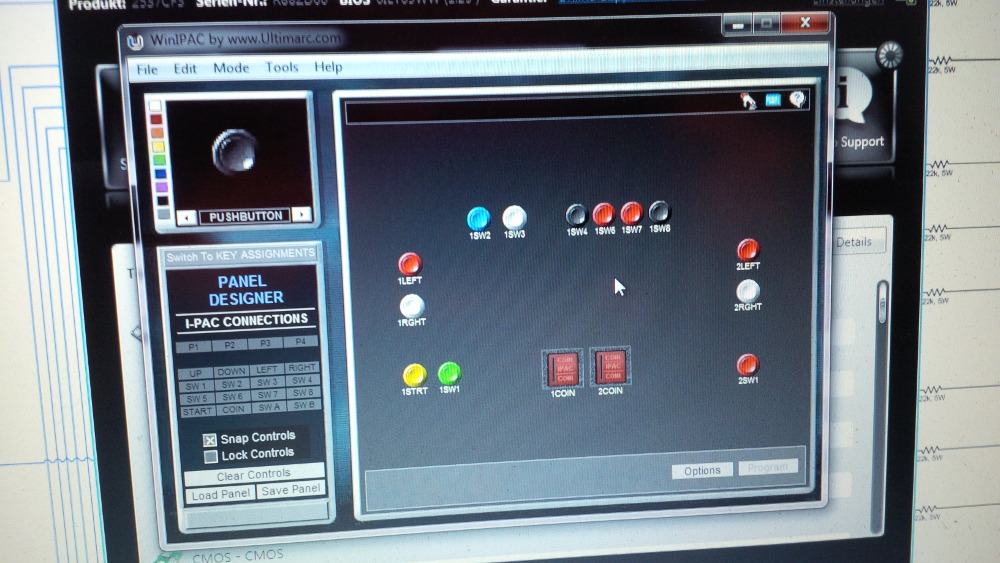
- You need a set of electronics. Boards like IPac or LEDWiz that are not easy to order or really expensive if you live outside the united states (shipping, tax). Contactors, LEDs, pinball buttons (leaf switches), a tilt/nudge solution, a digital (better analog) plunger solution, etc.
- You need a set of displays. What I found is that 46" displays is the biggest option suitable for widebody cabinet playfields. You need another TV for your backglass and a third one for a DMD replacement.
Hoooo f***! How to explain my wife that I want to spend several thousand bucks for a great thing that she call toy. Furthermore I am not sure if I own enough skillz to build something like Chris, Maxsinner, Zeb or all other great community members in this forum. There is a risk to end up in a mountain of expensive hardware, wood and pinball parts without a running result.
I am a fan of getting things running step-by-step - iteratively - reaching a milestone that makes fun before working on a next one. So I thought about an option to try this hobby before borrow money ;-).
After thinking, dreaming, thinking, crying, dreaming, thinking, it was time to do something!
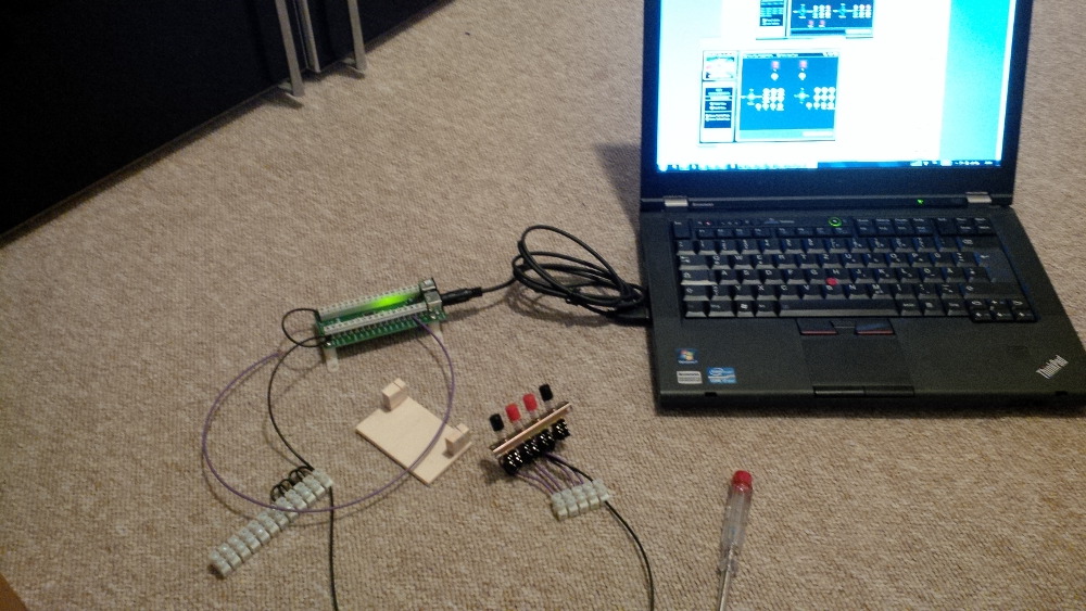
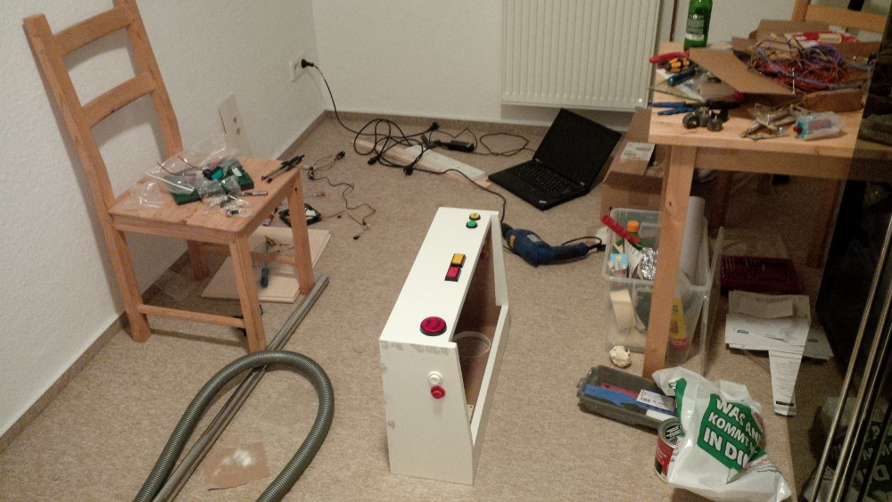
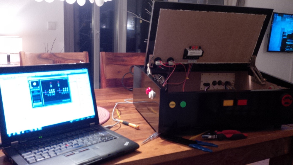
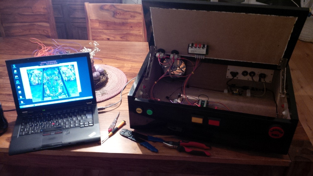
So I installed vp and downloaded my first table. After some error messages that ROMs are missing I downloaded every ROM that I could find related to the table and my first virtual pinball setup was up and running: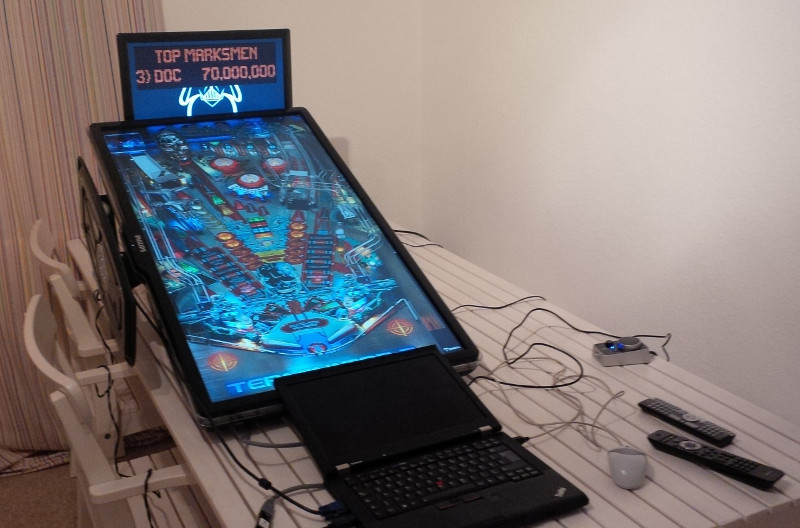
I used only hardware that already exist. An outdated thick LCD from our guest room, a small cheap LCD that my wife bought used for 20 euros (I had no idea what to do with the screen until this evening), my working notebook, a logitech 2.1 PC speaker/subwoofer set.
Coming soon: Chapter 2 - How to get inexpensive progress?
Edited by rasm, 15 December 2015 - 10:22 PM.


 .
.
 .
.
 .
.
 .
.
 .
.
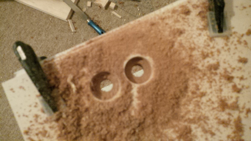
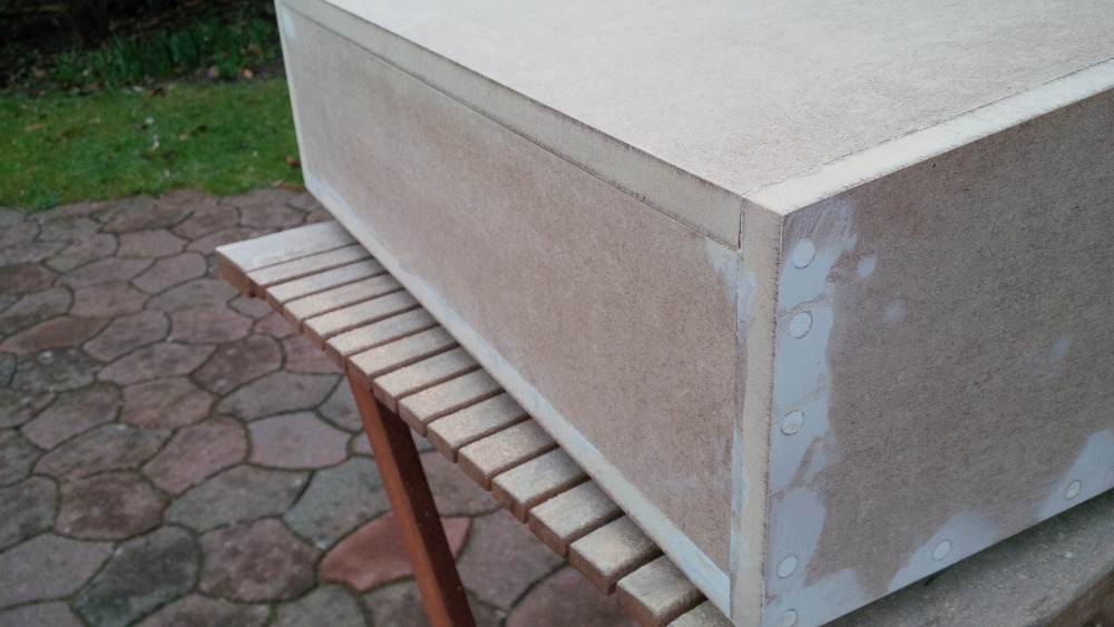
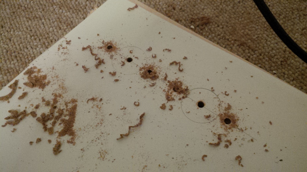
 It felt like really professional work,
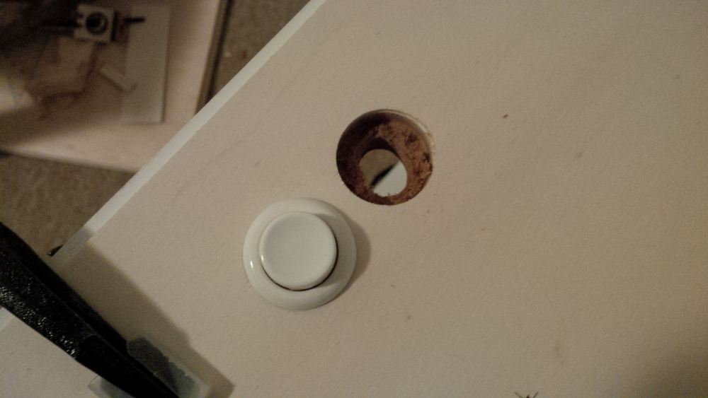
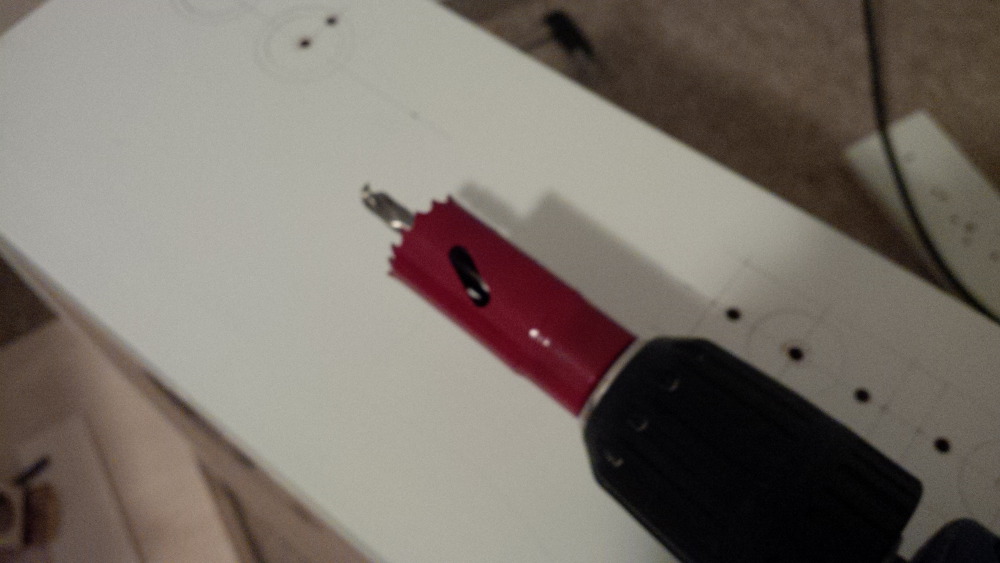
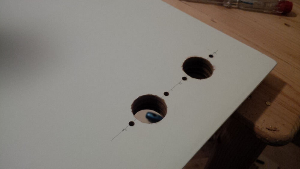
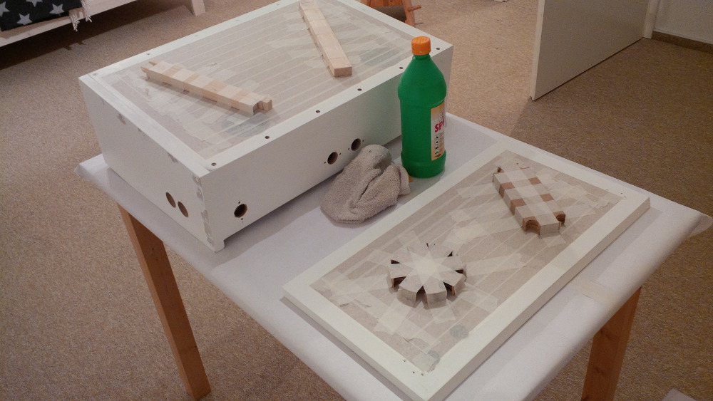
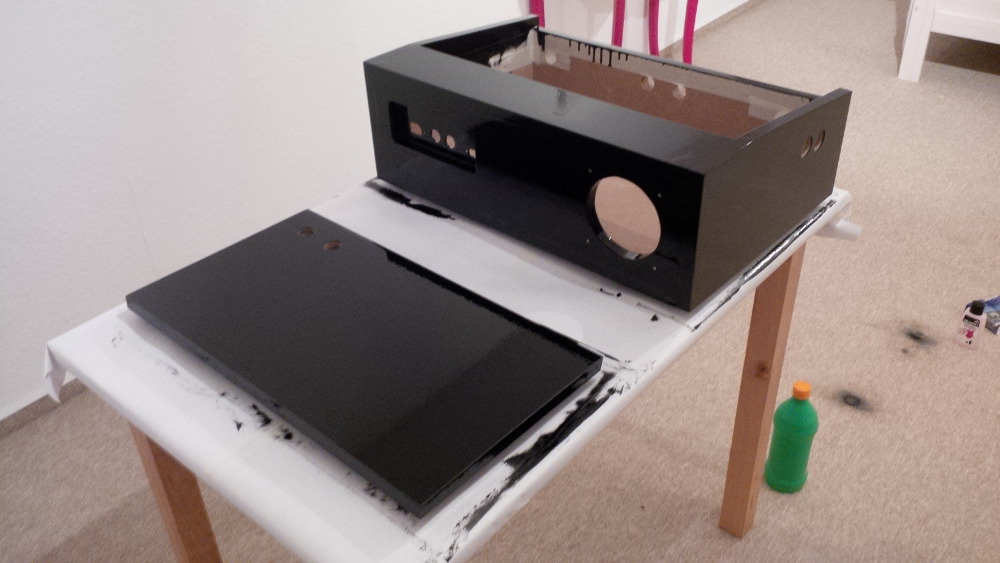
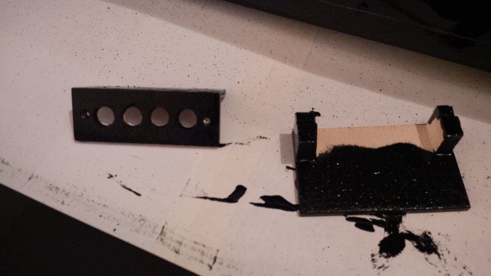

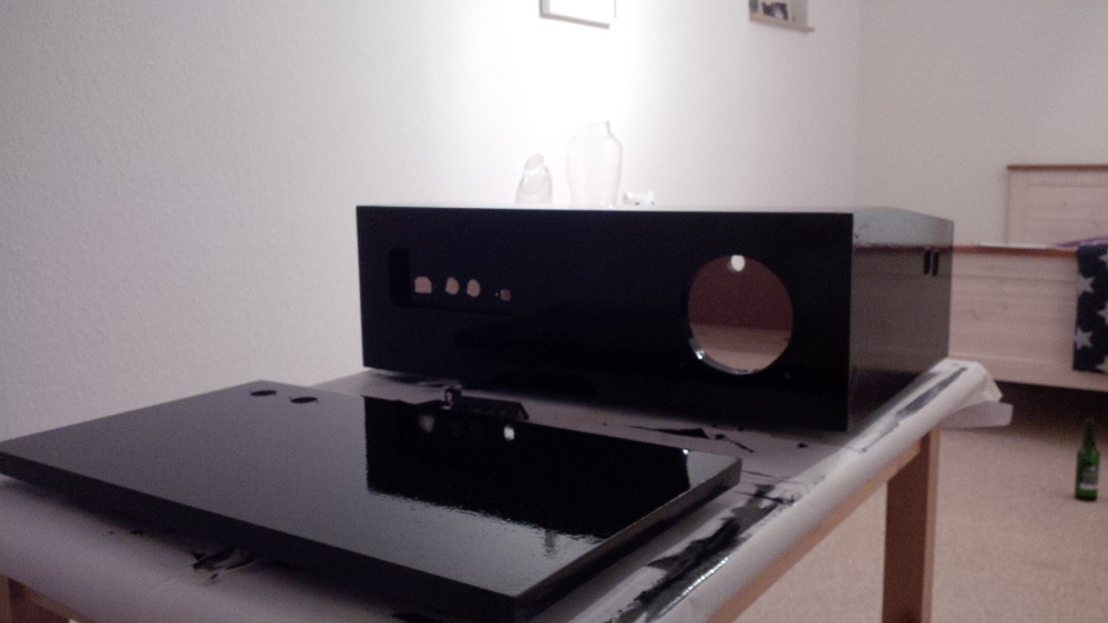


 . And the surface feels a bit strange, I cannot stripe my hand easily across it, it's a bit like rubber.
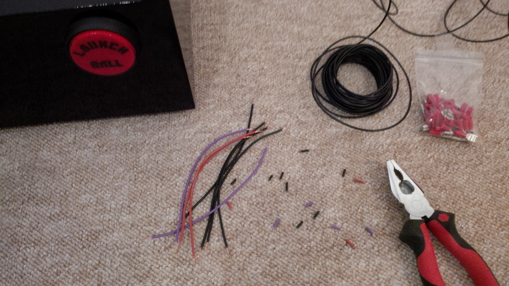


 are all trademarks of VPFORUMS.