Contributor
For coin door switch, here was a recent post:
http://www.vpforums....=27063&p=257023


 2 votes
Enthusiast


Posted 21 May 2014 - 10:50 PM
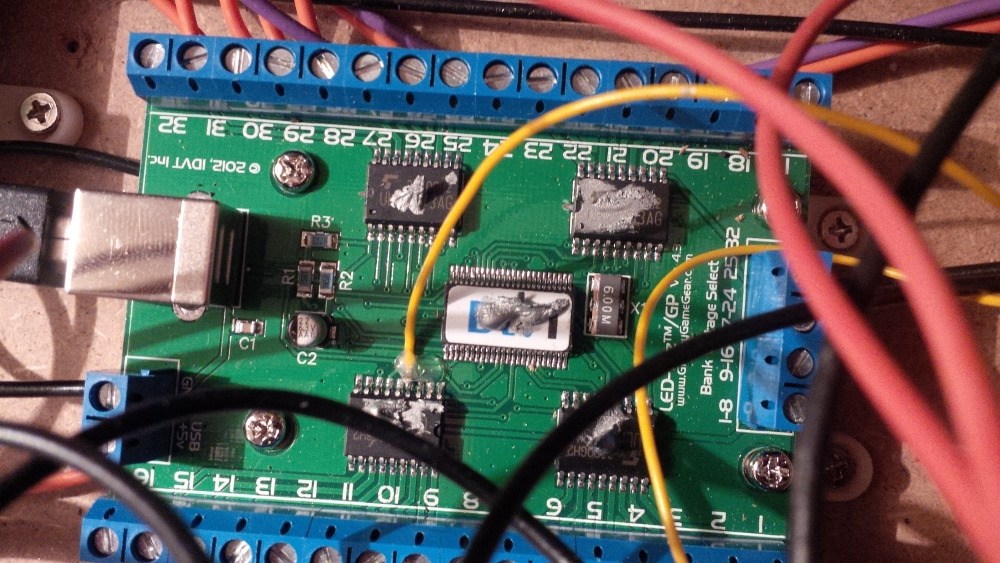
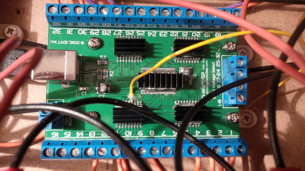
Chapter 14 - LEDWiz
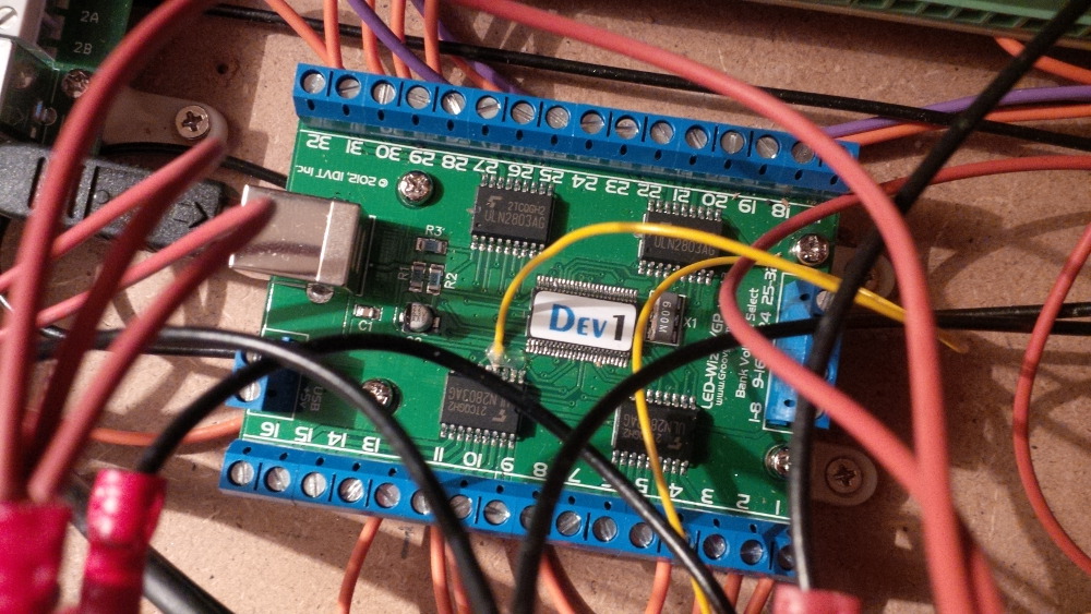
Uhhhh, I got excited... my LEDWiz arrived!
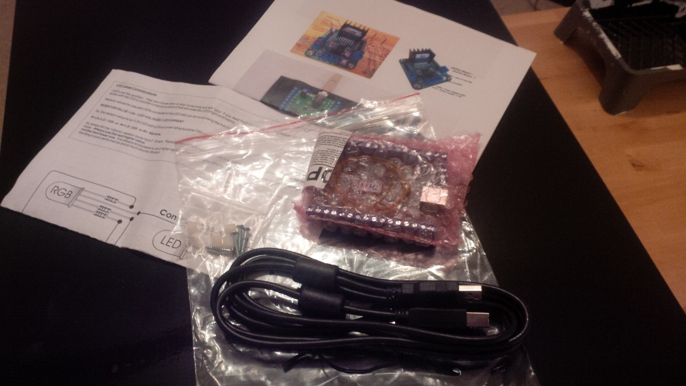
I directly mounted the LEDWiz, because it was the one and only task I could do. Without the accessoires like fuses I cannot use it.
One or two days later I got the fuse holders and terminal blocks.
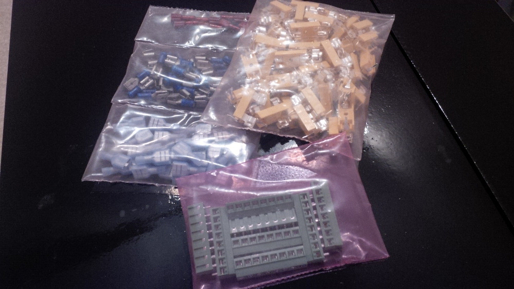
But the fuses and the blank board to setup a fuse block were still missing.
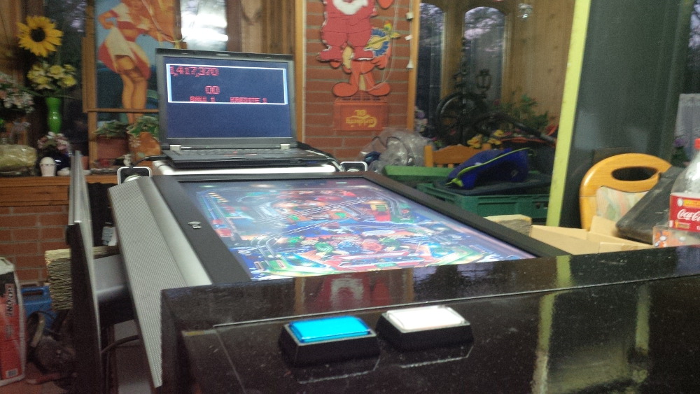
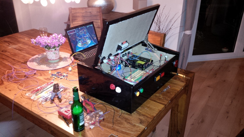
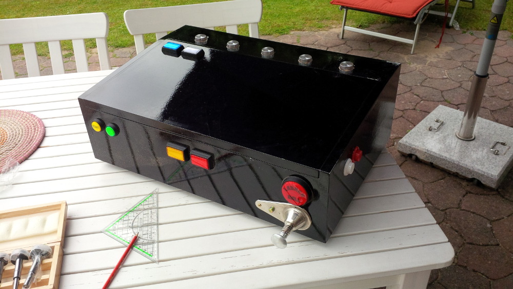
At this time I realized a big benefit of a small case instead of a real full size cab. We planned a short trip as family to visit friends for a whole weekend. And taaaadaaa, while my wife was rolling her eyes I put my pinball box in the luggage space, grab my notebook and made my baggage complete by the speaker/subwwofer set and some cables, hihihi. A real cab is always the best option, except you travel around.
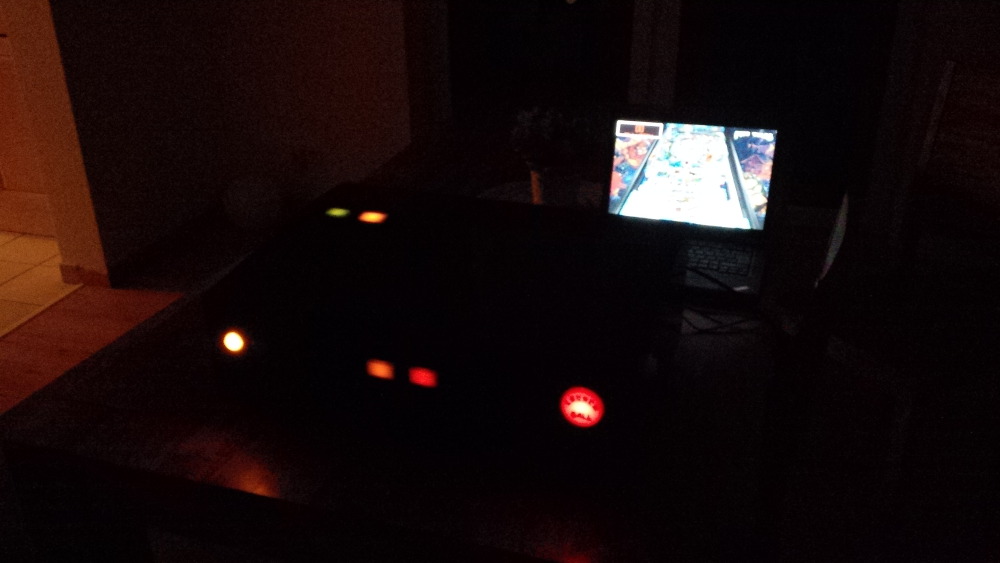
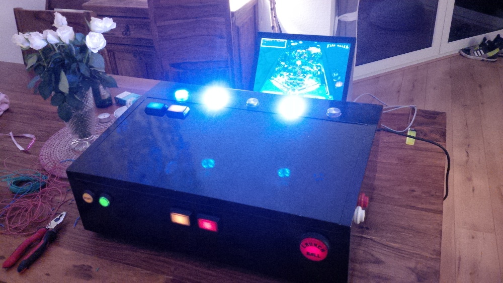
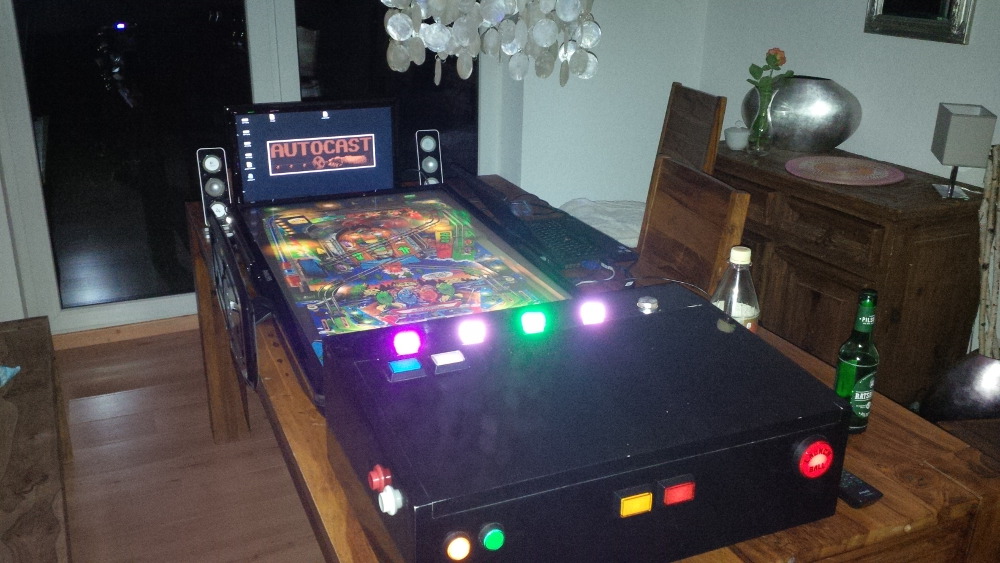
After we arrived my friend heat up the BBQ and we moved an old LCD to a makeshift table in his party loggia and setup the pinball box fasten. He was impressed and we had a lot of fun with the tables we played together as children.
It wasn't a surprise (at least for him) that I had my box with me, because we had some calls about it. He's a mechanic and I thought this could be the best man to organize some starter solenoids to support my force feedback plans. Yea, he was absolutely willing to support me and I am pleased to say thank you on this way. I was very interessted what solenoids he got and I promised two bottles of wine. He prepared all solenoids together with a car battery to demonstrate the firing effects. When I saw his setup I couldn't believe my eyes. My requirement was that these solenoids must really give a feedback and he absolutely fulfilled this need. How I could mount this stuff in my box? No idea. For what effect could I use these impressive big slow solenoids? No idea.
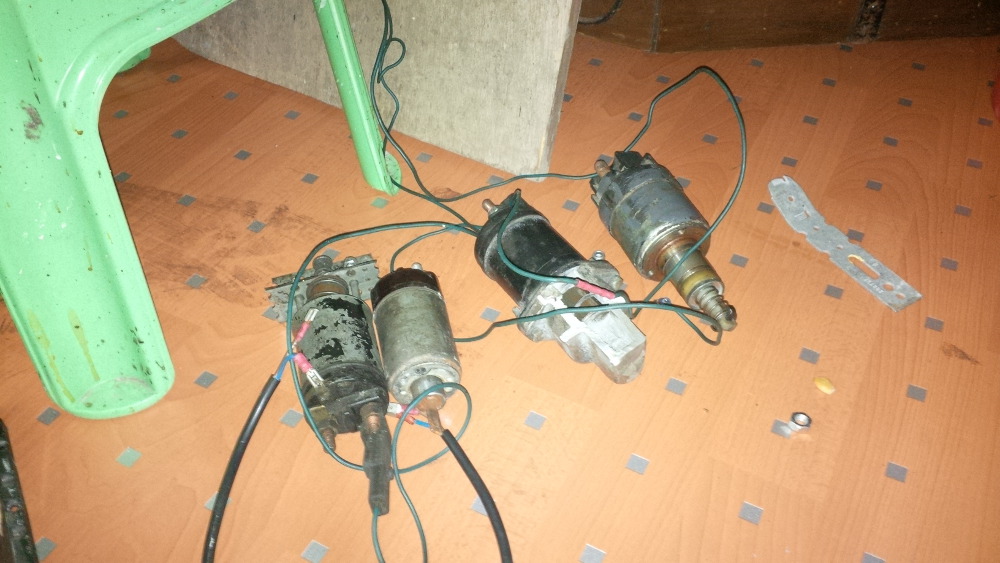
Maybe I could wire them in a sequence to replace a shaker motor ;-). Any ideas are welcome.
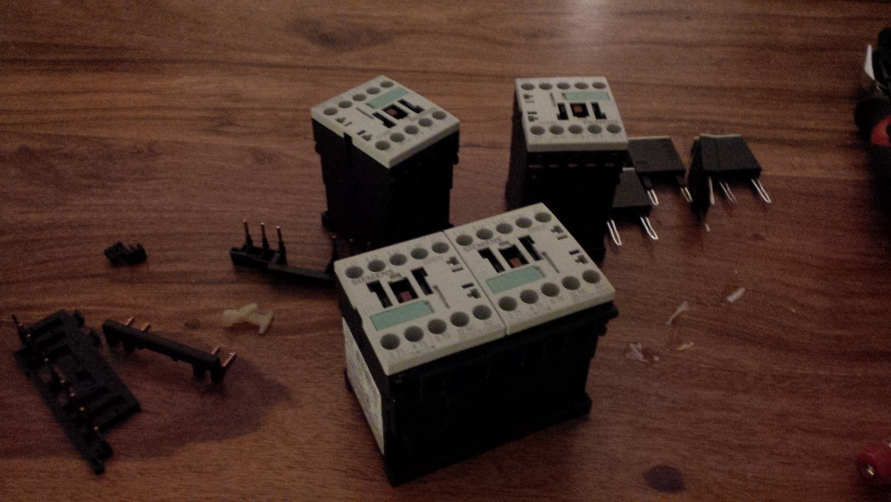
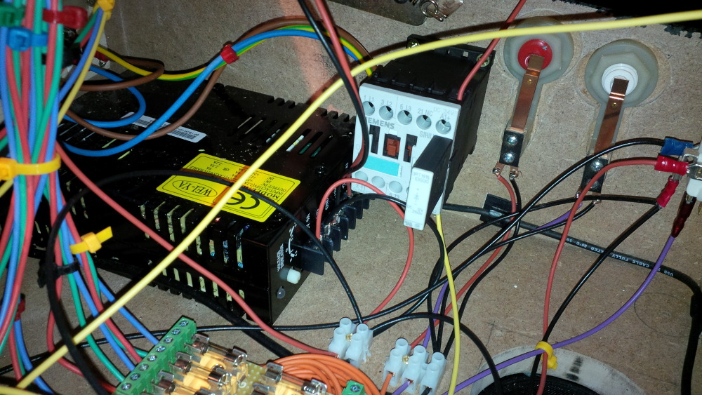
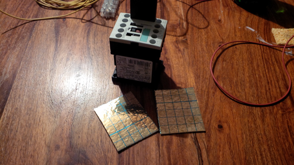
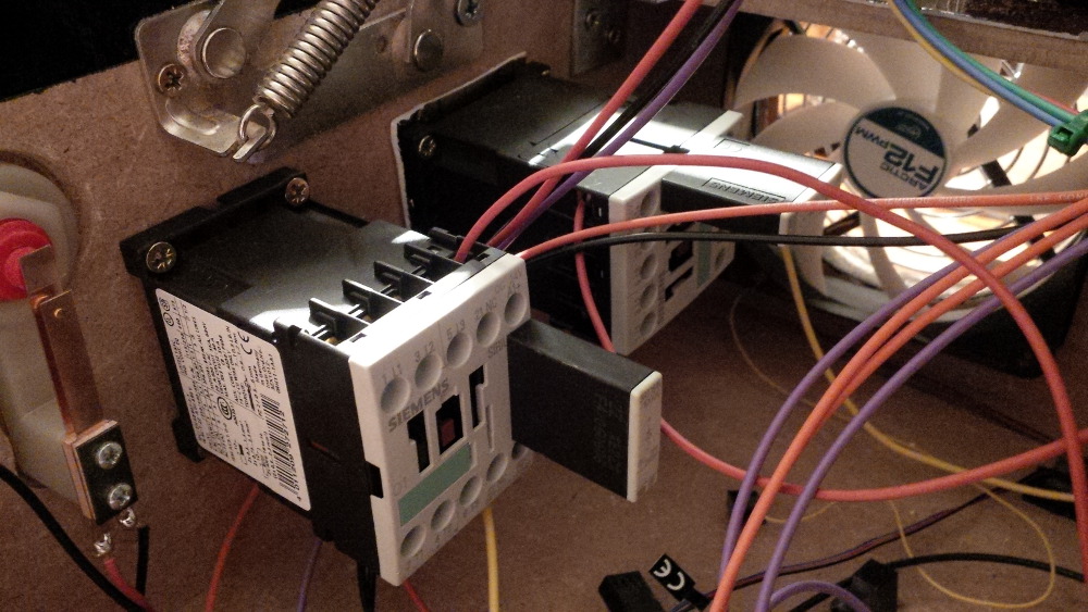
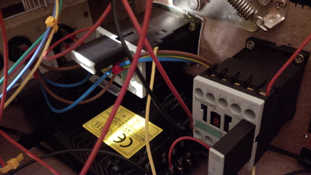
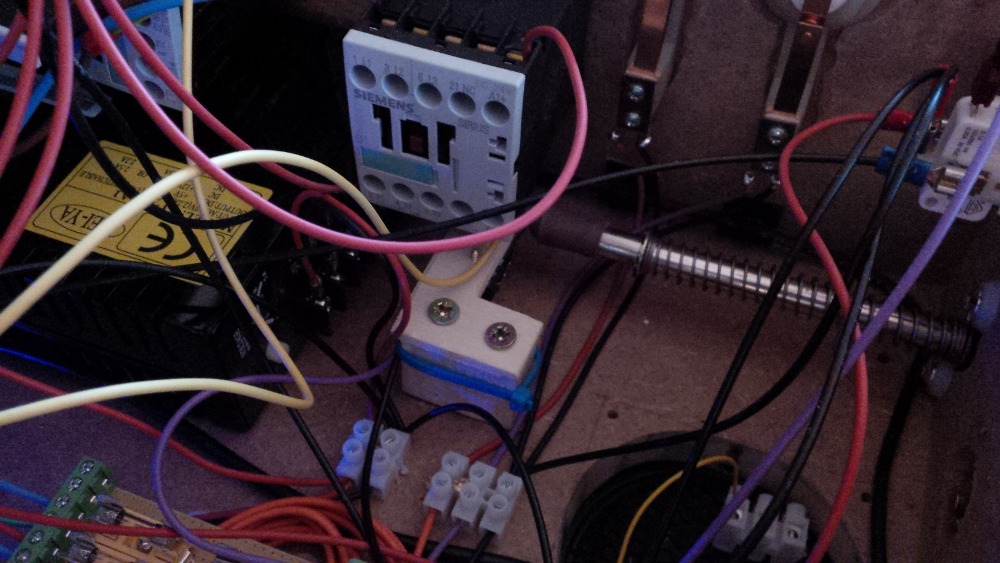
Back at home I searched at ebay for contactor auctions and made a bet on a set of four 24V Siemens Sirius at least for the flipper and slingshot effects. Furthermore I was happy that the fuses was arrived.
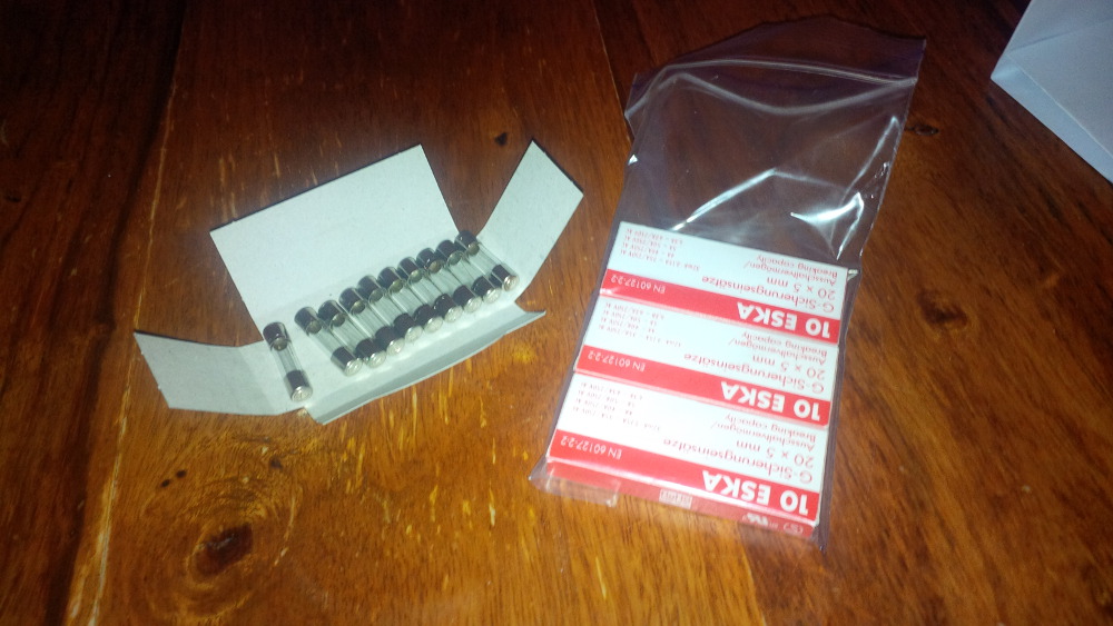
I started to plan my fuse block especially the size, because it is limited in my setup when I want to integrate more toys.
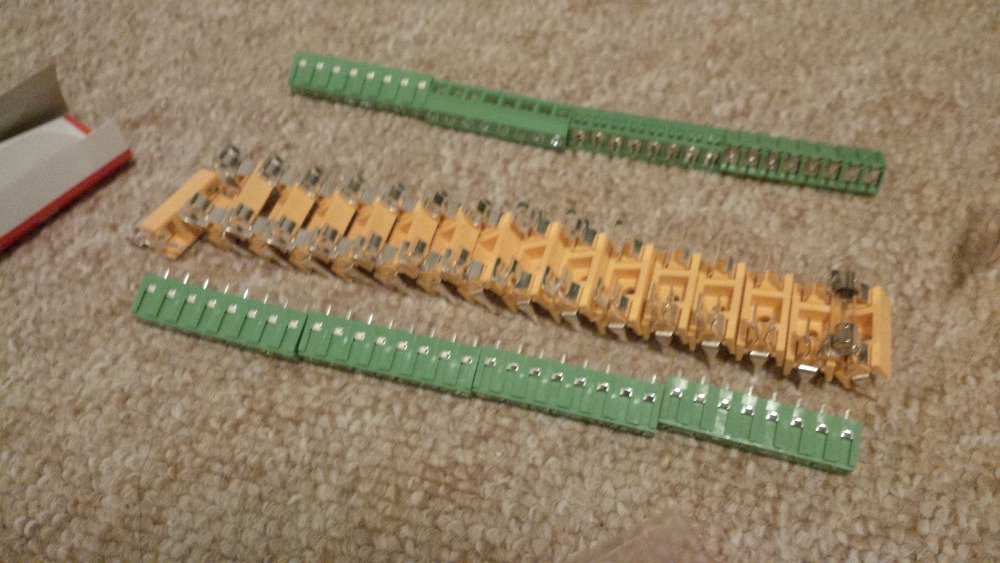
A few days later I got a set of blank boards and I directly began to solve the precondition to see my LEDWiz in action. The fuse holder pins were a bit to big for the board holes, but luckily I own a drill.
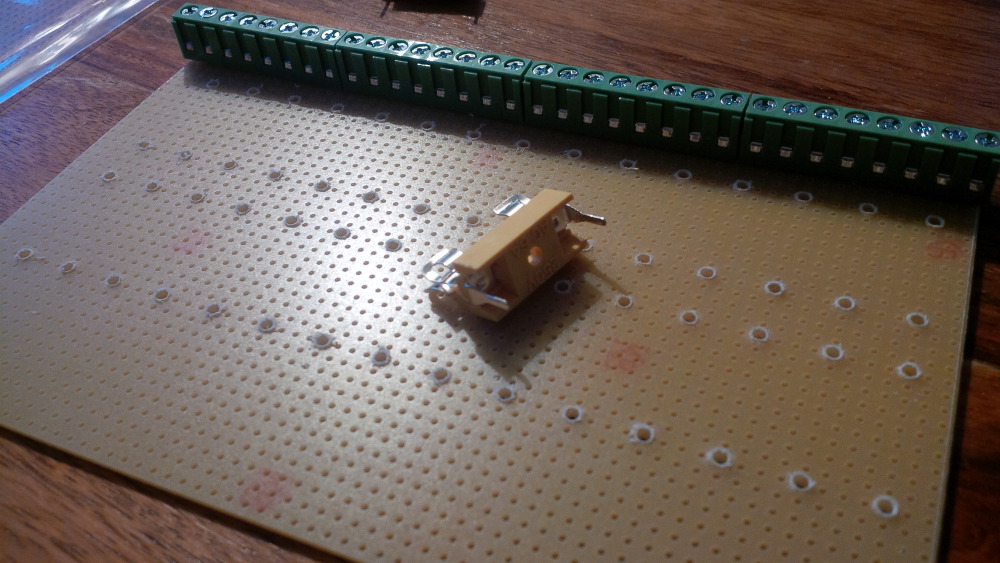
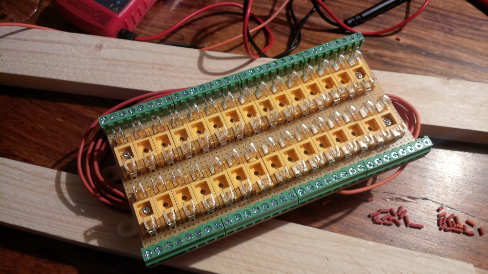
I only got 30 fuse holders on the board size. But okay, than two toys will get dedicated fuses if needed. I put the first row holders on the board...
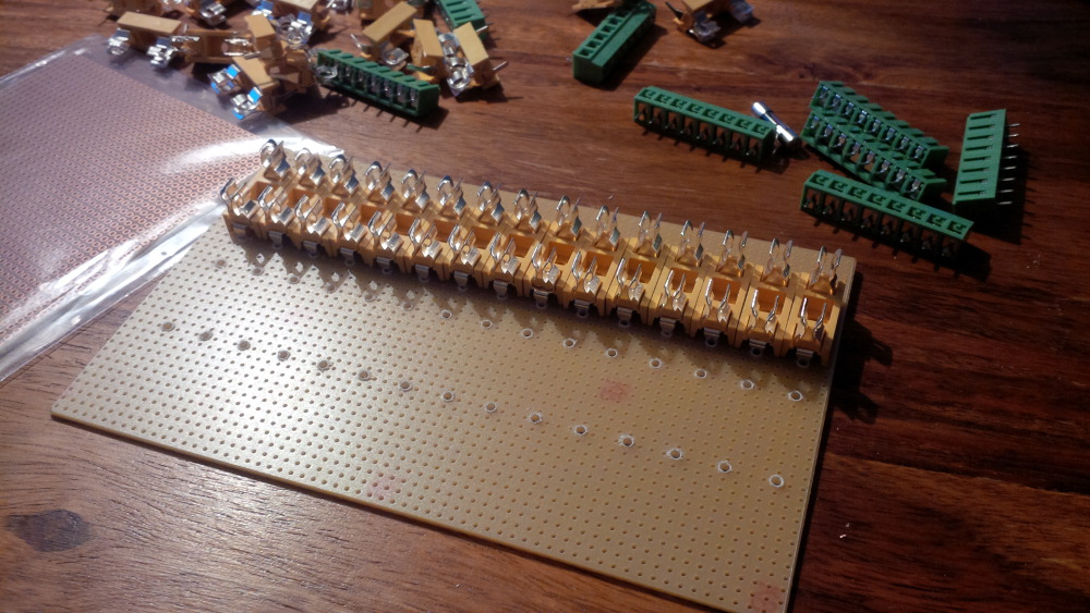
...and a second one...
...and quickly fastening them by crippling the pins.
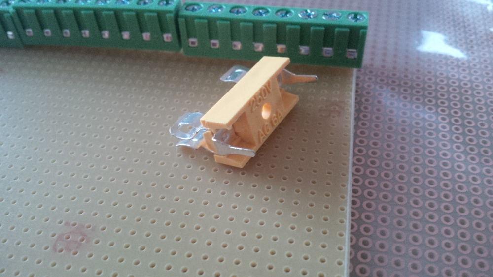
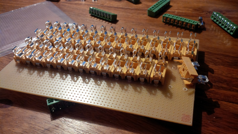
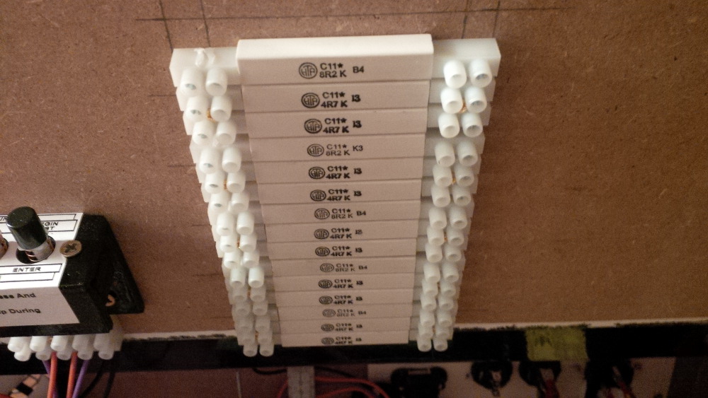
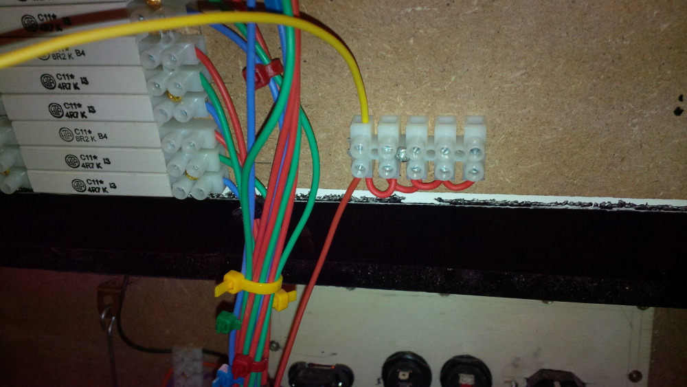
After putting in the terminal blocks the board layout looks fine - my fuse block.
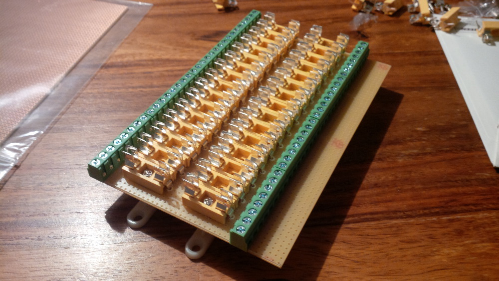
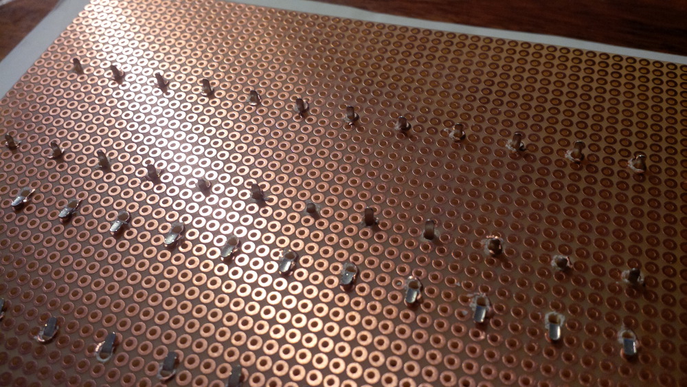
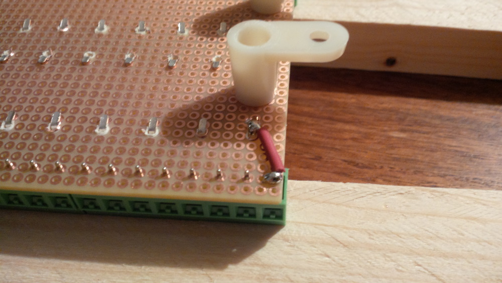
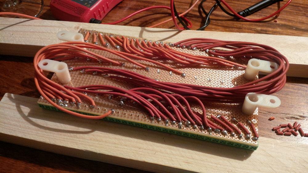
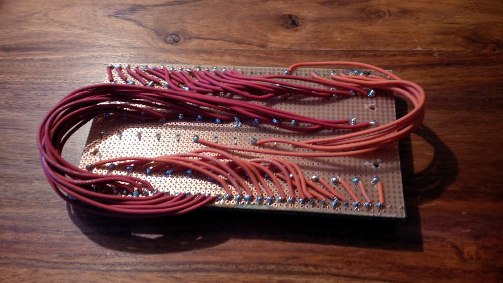
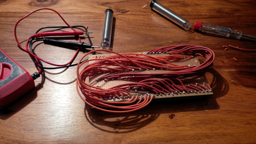
It looks almost finished, but the real effort behind this component still waits for me. Probably it was a really stupid idea, but I thought it makes sense to solder wire connections between the terminal blocks and every single fuse holder. Uhhh, that means 30 input connections + 30 outputs = 60 small wires to solder. I was motivated while having my LEDWiz in mind and started the marathon.
The first wire...
Some more wires...
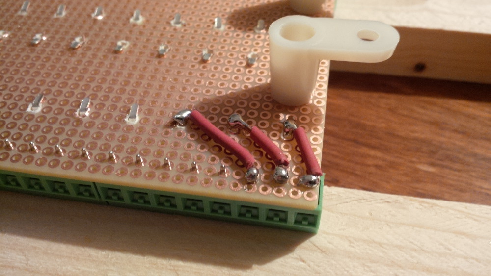
This task takes several hours and feels like crochet job. I stopped very lately when my tin-solder was empty.
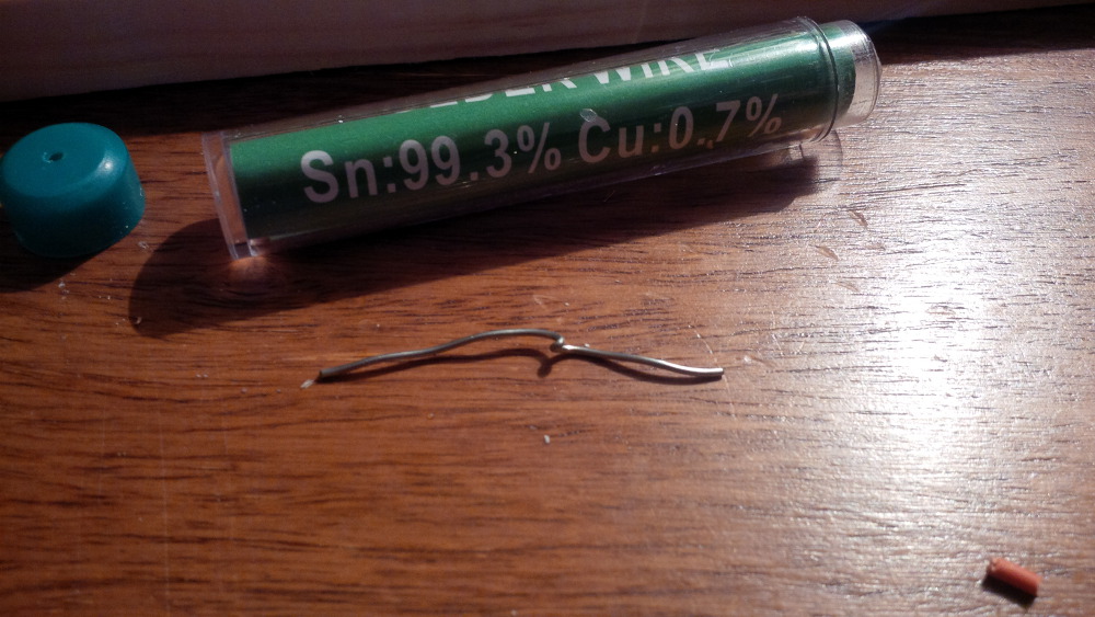
So I ordered some more of these stuff, took a last look of the result and went to sleep.
Visit my build: Yet another build thread
Enthusiast
Posted 21 May 2014 - 11:03 PM
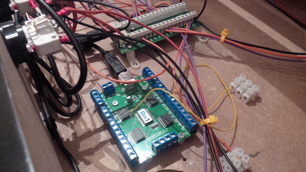
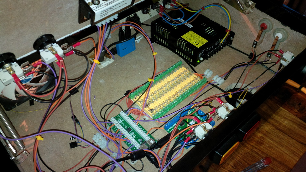
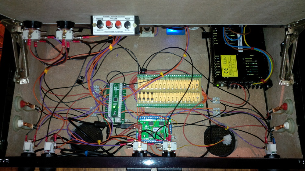
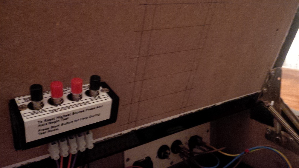
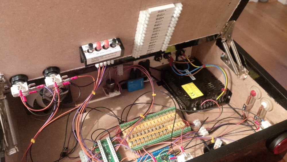
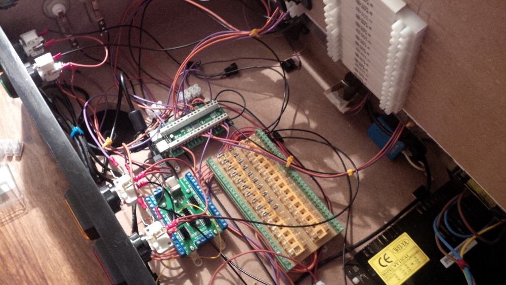
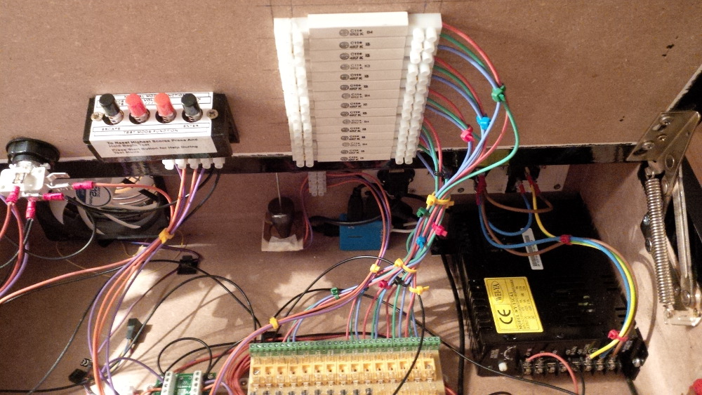
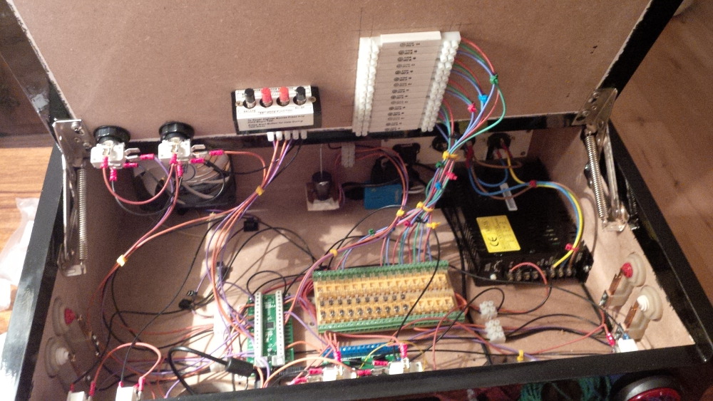
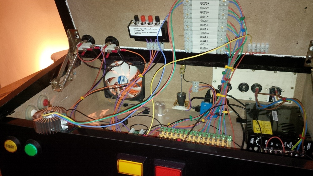
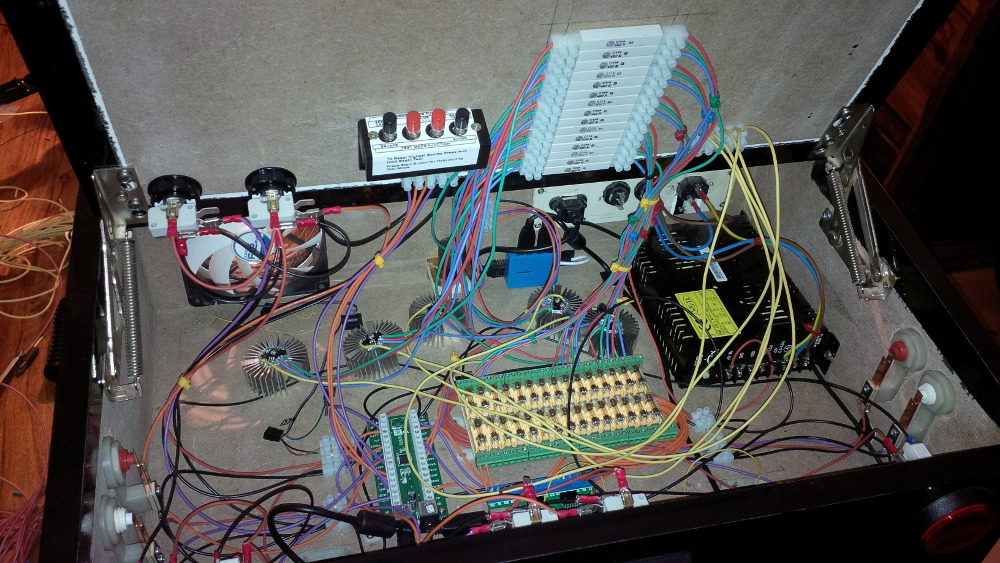
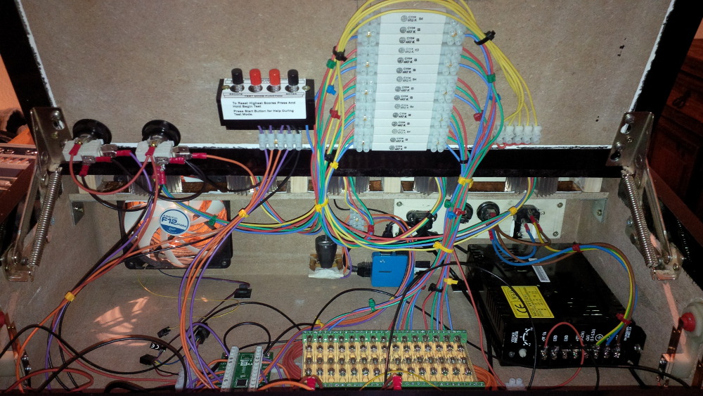
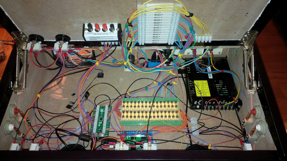
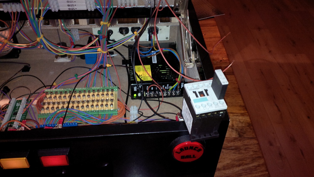
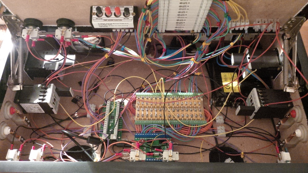
On the next day I got a brand new power supply (a real one yet) and an USB hub, so that I am able to connect both boards (IPac + LEDWiz) with my single USB connector. Additionally you will get a nice side effect by using an USB hub for your hobby projects. If something went wrong you won't blow the USB controller of a mainboard, you only would blow a hub that costs a few bucks.
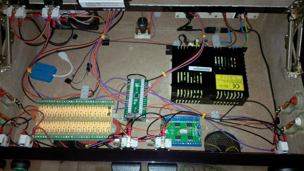
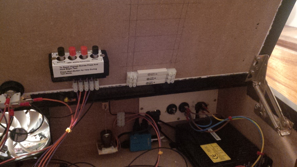
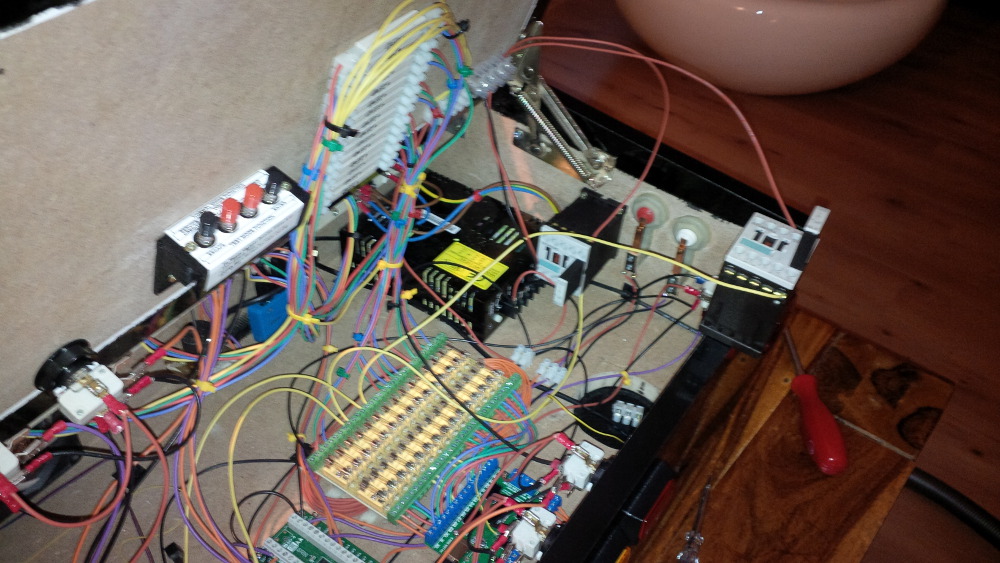
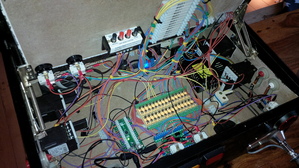
After moving around the components in my case I noticed that it is small (but not too small). I decided to mount the power supply near to the main power connection. I moved the IPac a bit more to the left and got place to keep LEDWiz and fuse block close together.
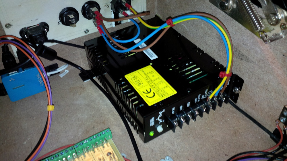
The power supply from arcadeshop looks quite nice. I chose a variant with 130 watt that delivers 9A on +5V, 4A on +12V and 1.5A on 24V, so that I could use a wide range of toys. The +5V output can be accurately adjusted.
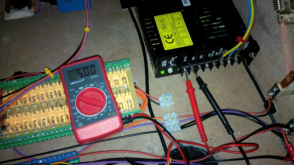
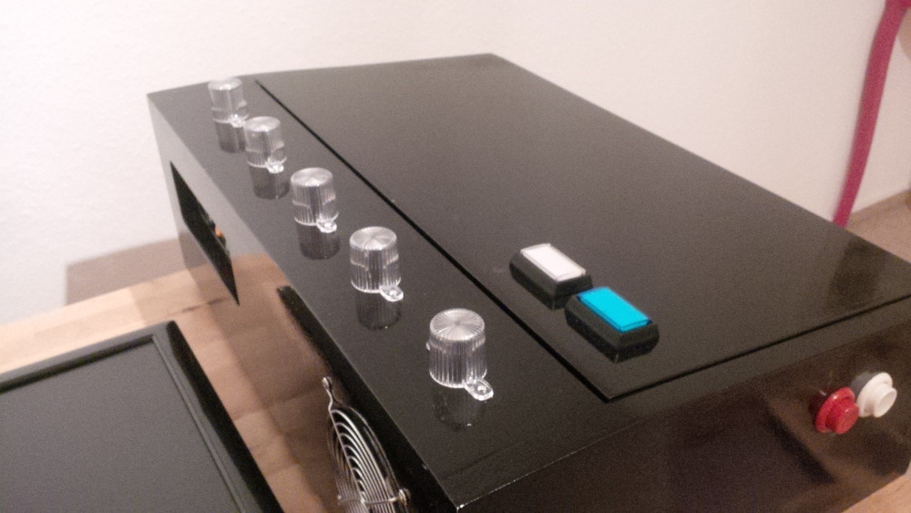
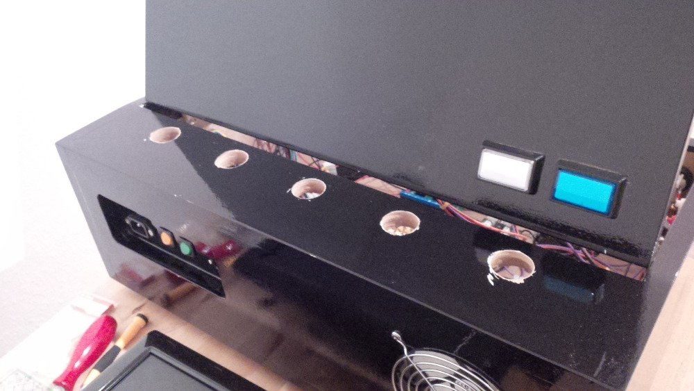
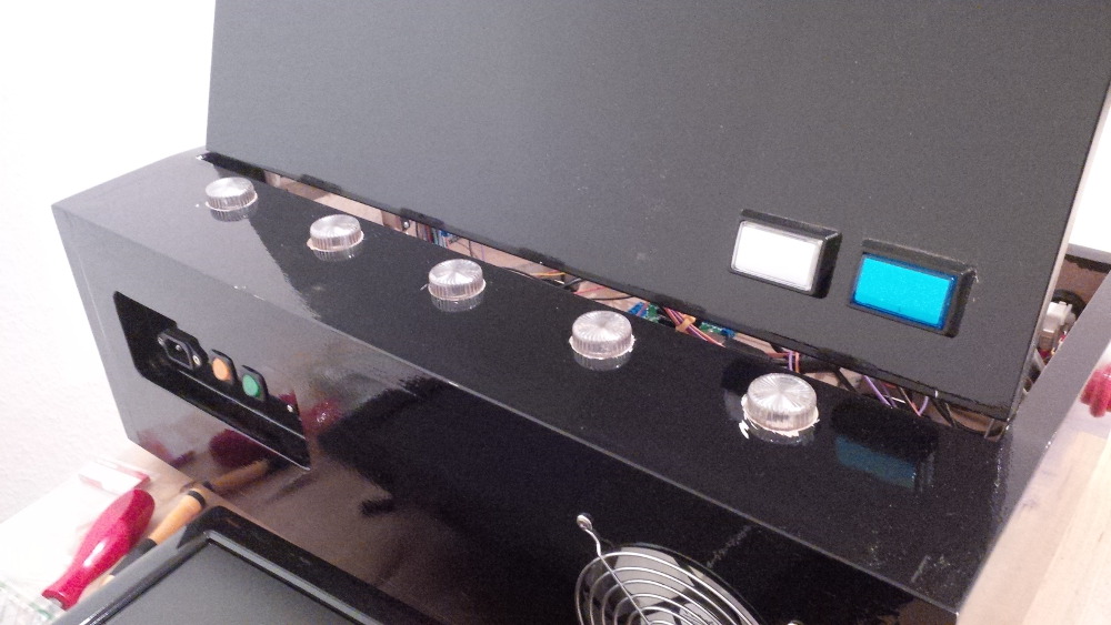
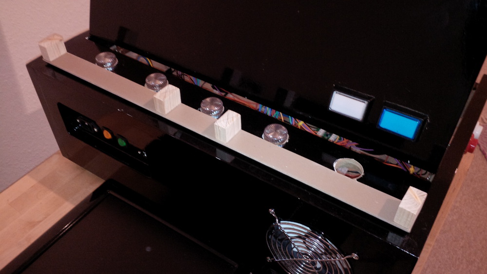
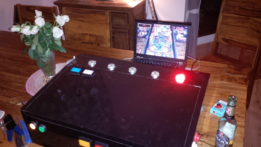
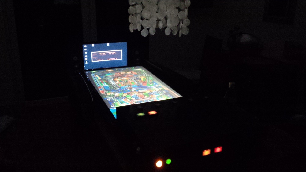
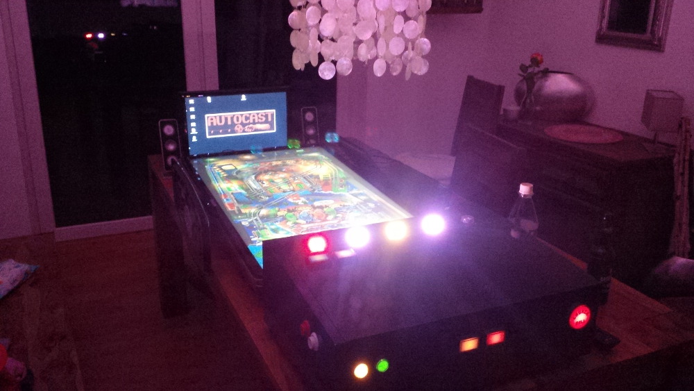
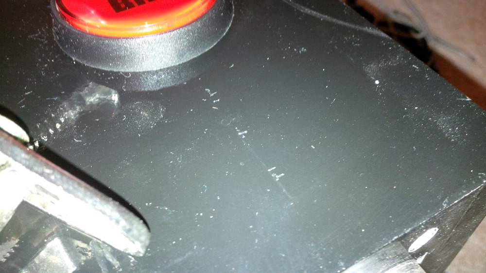
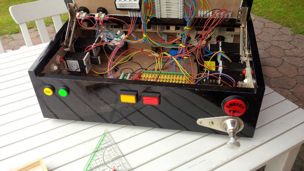
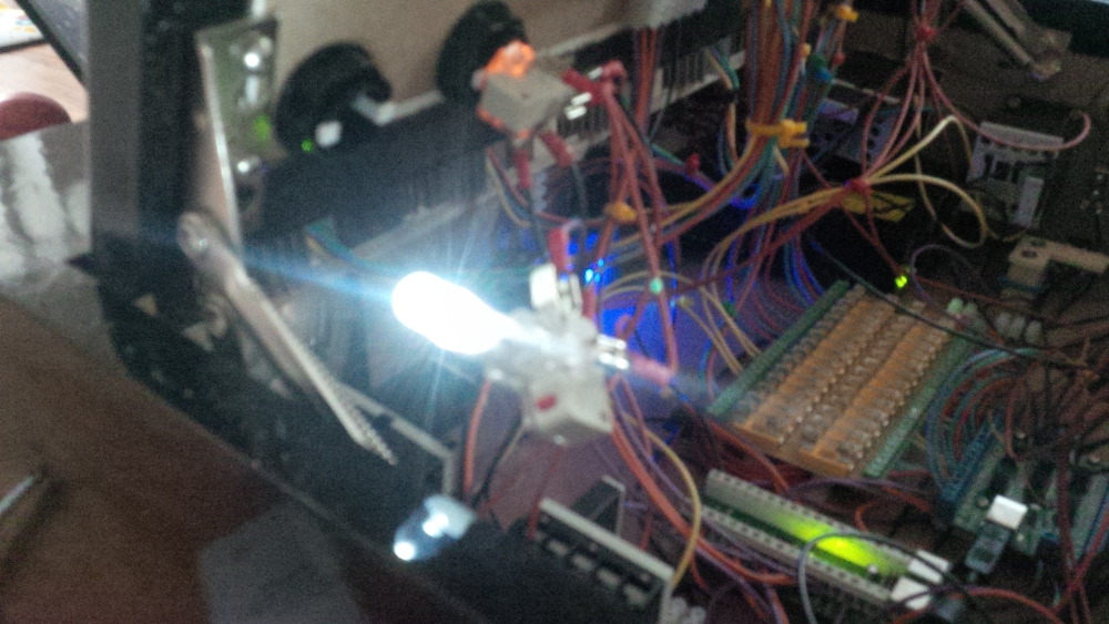
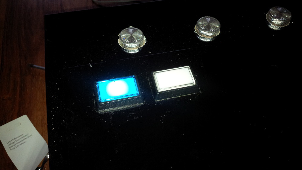
I connected the 5v line and got my buttons lights on as expected. The yellow start button is still brighter...
Sure, the fuse block isn't complete, but I have enough ports finished to start wiring the LEDWiz. To keep things simple I connected my buttons to let them blink rom controlled.
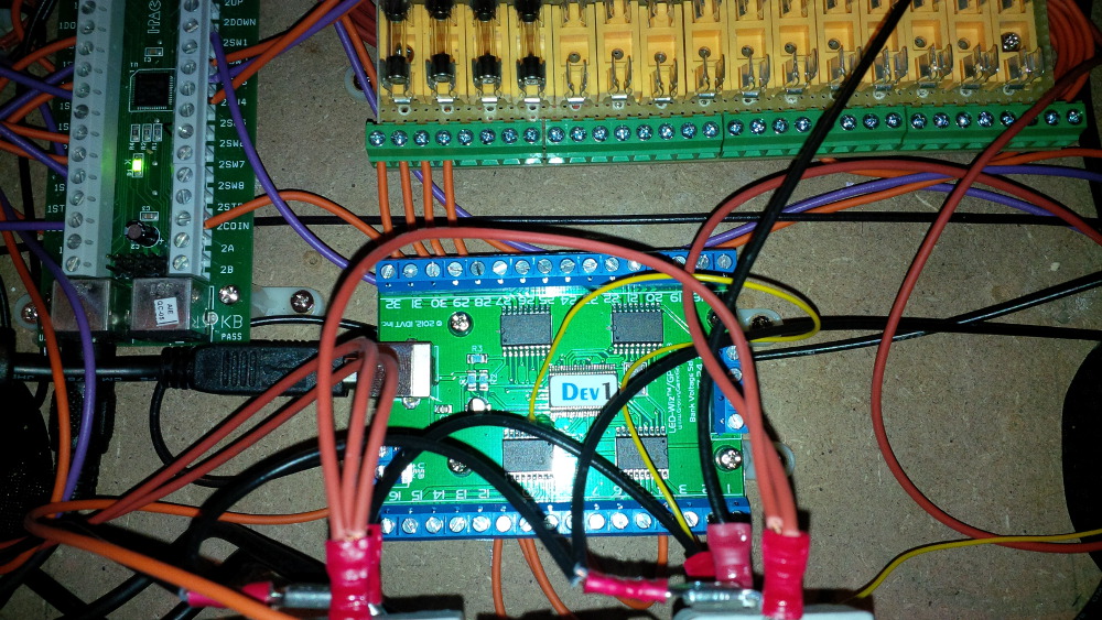
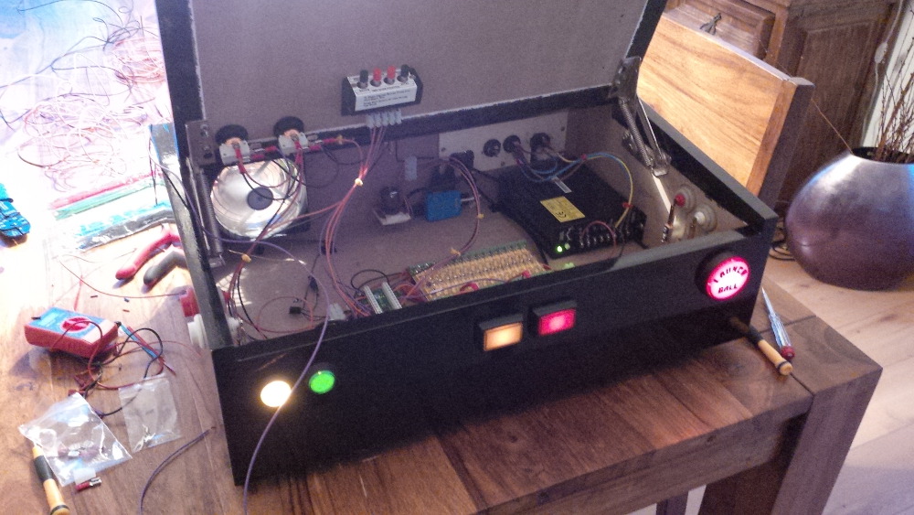
And yes! It works! I reached milestone III.
I connected the following buttons to my LEDWiz:
I will disconnect the extra ball button and the coin buttons from my LEDwiz and wire them directly to the power supply later. Related LEDWiz ports can I use for more fancy effects.
Ahhhhh, it felt good to make progress.
Coming soon: Chapter 15 - Resistors and some heat sinks
For coin door switch, here was a recent post:
Nice.Thx, I will try this approach.
Edited by rasm, 22 May 2014 - 06:10 AM.
Visit my build: Yet another build thread
A Faint Ghost Through the Raindrops


Posted 22 May 2014 - 05:14 AM
Very cool. I have created traveling pinball controllers as well, my first one was a bit ugly but it did the job.
I should make a new version, this was just using arcade buttons, I want to get real flipper buttons. This was tailor made to this TV as well, so it clamps around the end. Arduino controller inside.

Enthusiast
Posted 22 May 2014 - 06:17 AM
Very cool. I have created traveling pinball controllers as well, my first one was a bit ugly but it did the job.
I should make a new version, this was just using arcade buttons, I want to get real flipper buttons. This was tailor made to this TV as well, so it clamps around the end. Arduino controller inside.
...
Thx. Wow - the build of tailor is very small. Arduino is currently a kind of magic for me. Together with some relays I think it should be able that a single controller replaces IPac and LedWiz - probably it's more hard to get enough output current, but for this case relays could be used.
I slowly recognized at this stage of my build that I have not much space in the case to integrate a lot of toys. When screwing something to the case I would have to break my fingers. Luckily I got enough motivation to at least try to integrate as much as possible. And I was really looking forward to setup force feedback... Next chapter coming soon...
Visit my build: Yet another build thread
Enthusiast
Posted 22 May 2014 - 10:13 PM
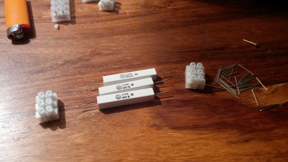
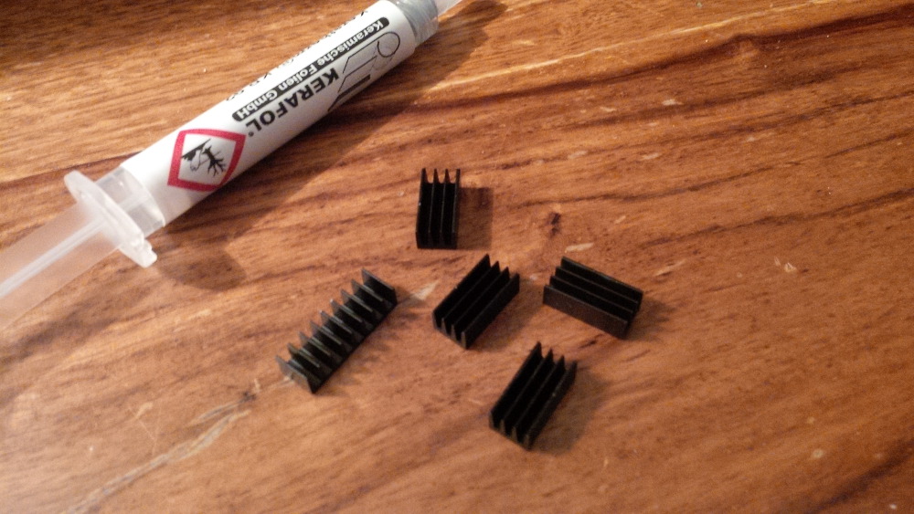
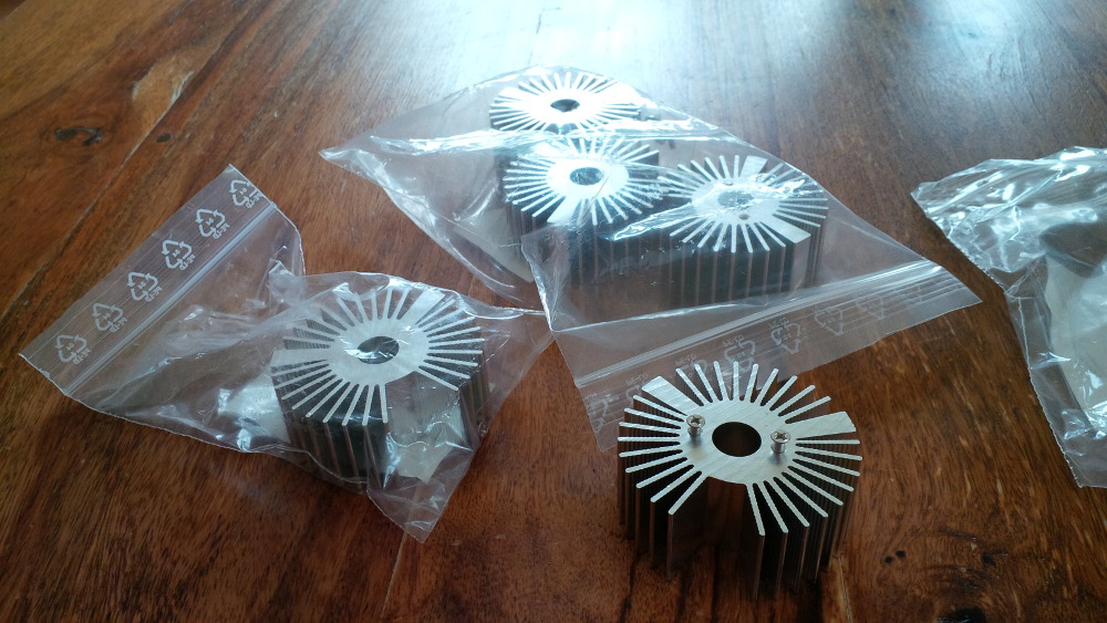
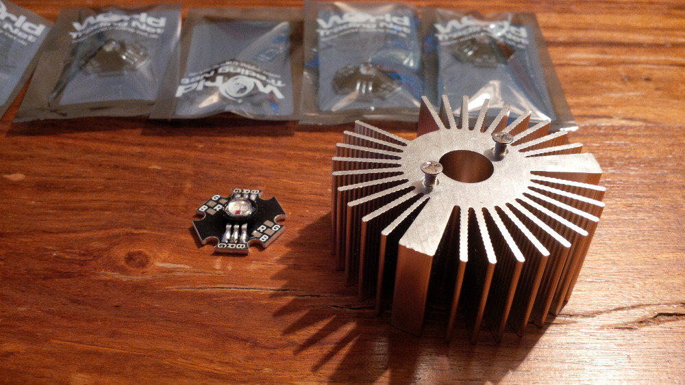
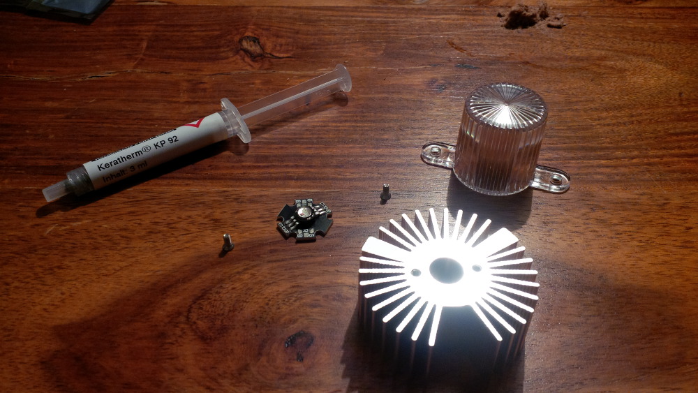
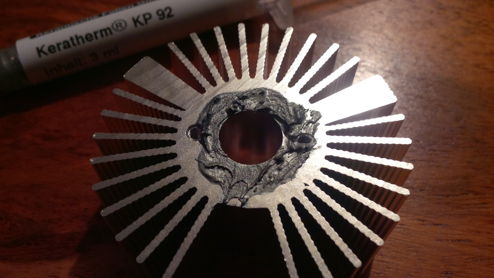
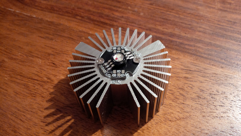
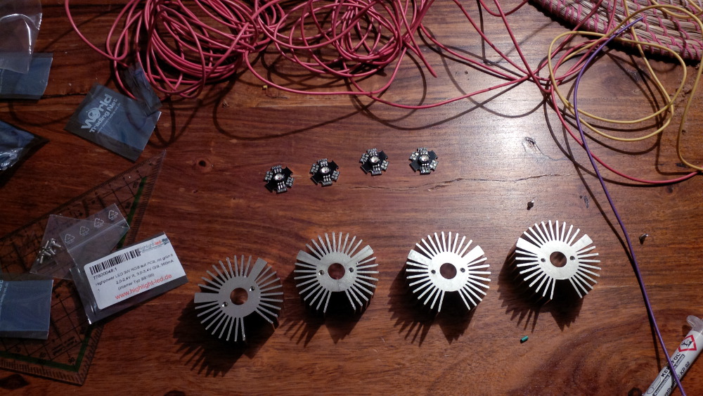
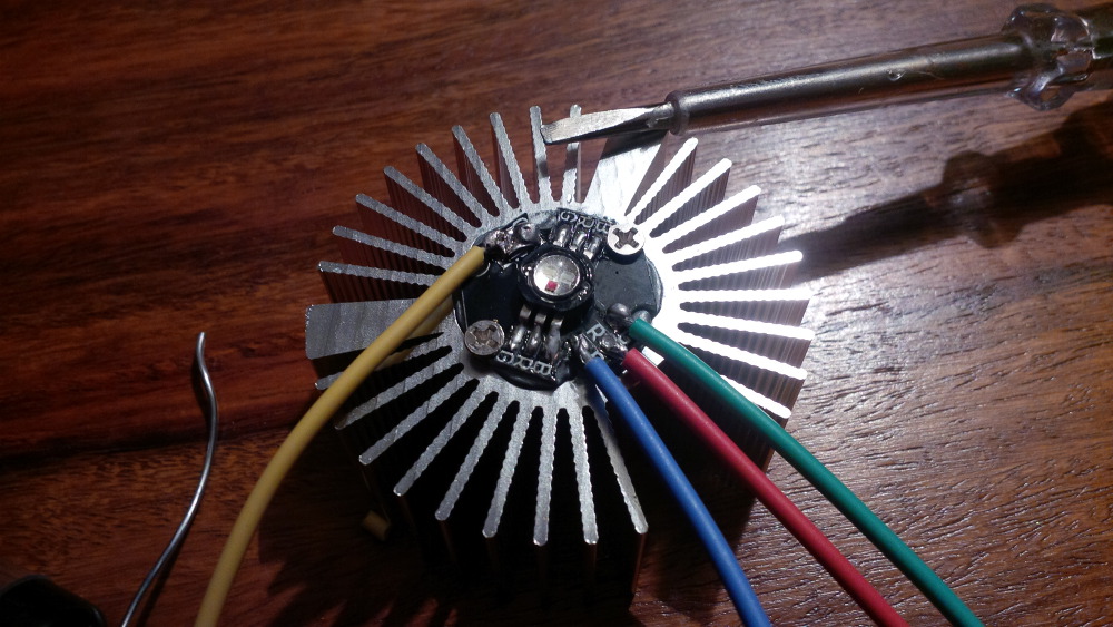
Chapter 15 - Resistors and some heat sinks
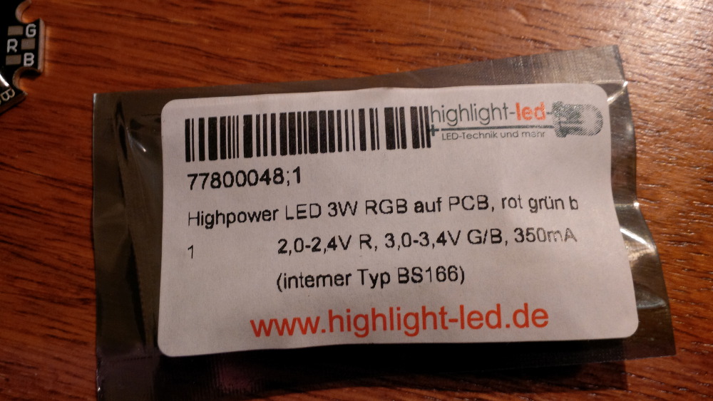
R      = (USupply - UNeed) / I
RRed   = (5V - 2.4V) / 350ma = 2.6V / 0.35A = 7.43ohm
RGreen = (5V - 3.4V) / 350ma = 1.6V / 0.35A = 4.57ohm
RBlue  = (5V - 3.4V) / 350ma = 1.6V / 0.35A = 4.57ohm


Visit my build: Yet another build thread
Enthusiast
Posted 22 May 2014 - 10:27 PM
Chapter 16 - Crocheting
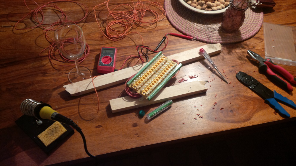
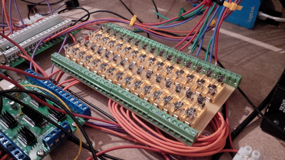
Okay, this chapter is a bit boring, but I want to share a full documentation. If you read this thread you know that my fuse block isn't completly finished. I got new tin-solder and did it.
Last status...
New tin-solder...
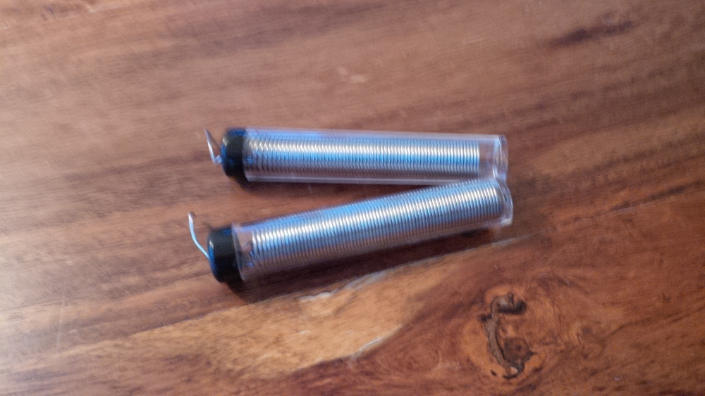
Hopefully a last time crocheting...
Done! 30 mounted fuses to have safe fun.
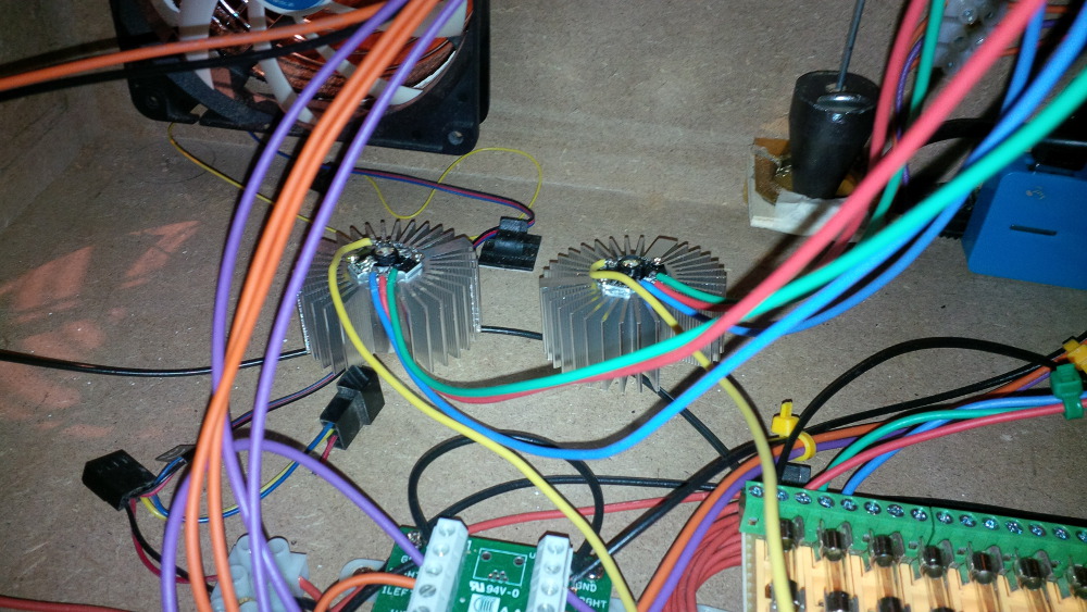
Coming soon: Chapter 17 - Flasher
Visit my build: Yet another build thread
Posted 23 May 2014 - 12:29 AM
Enthusiast
Posted 24 May 2014 - 08:35 PM
Visit my build: Yet another build thread
Enthusiast
Posted 24 May 2014 - 09:28 PM
Nice build
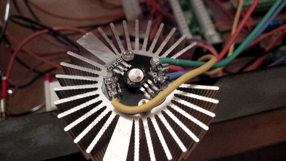
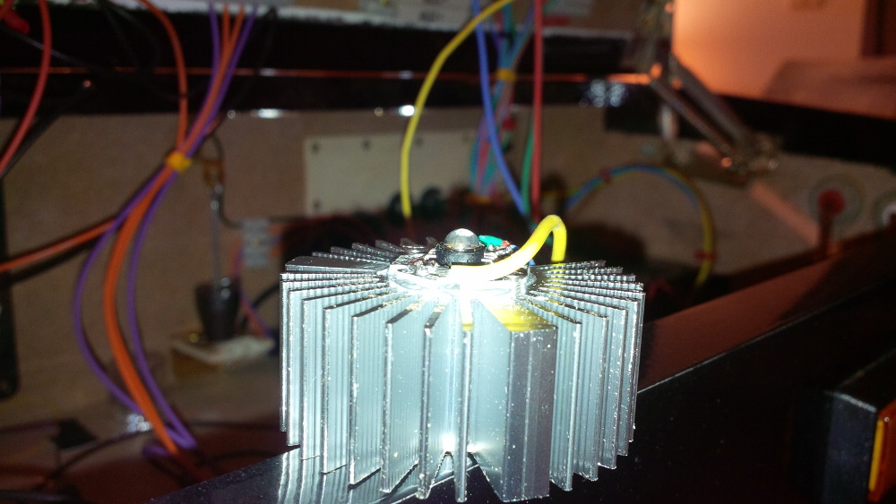
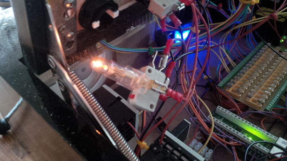
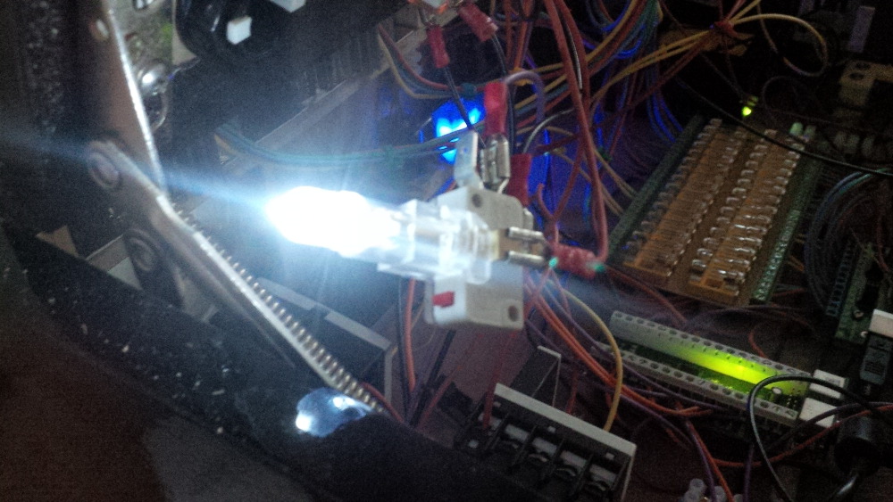
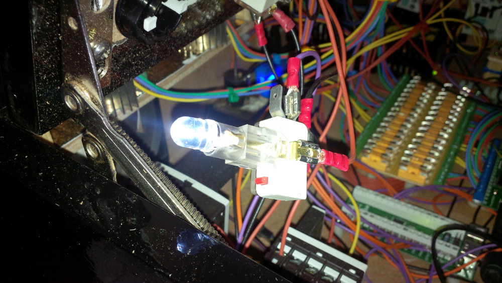
Wire 1 flasher first and test it before proceeding with all of them. Some of the cheap LEDs are marked incorrectly.
For testing the LEDs try using the "SimpleLEDTest.exe" that comes with the LEDBlinky app (http://www.ledblinky.net/Download.htm).
Thx, gtxjoe. You're absolutely right. I had to test my LEDs before wire them to prevent errors or effort on defected components. I simply checked every color of every LED to...

Edited by rasm, 24 May 2014 - 09:29 PM.
Visit my build: Yet another build thread
Enthusiast
Posted 24 May 2014 - 09:59 PM

Visit my build: Yet another build thread
Enthusiast
Posted 25 May 2014 - 07:42 PM
Great thread! Your doing a great job and I enjoy your posts! Keep them coming.
Agree with randr .... A+
Great humor too, a la the carper repair via the rocking horse.
. You are an excellent writer and this is a fantastic thread
Oh wow, thx for your compliments. That really boost me up to do more  .
.
Visit my build: Yet another build thread
Enthusiast
Posted 25 May 2014 - 08:47 PM
Visit my build: Yet another build thread
Enthusiast
Posted 01 June 2014 - 08:55 PM
 .
. .
.
Visit my build: Yet another build thread
Enthusiast
Posted 01 June 2014 - 09:33 PM
Edited by rasm, 01 June 2014 - 09:34 PM.
Visit my build: Yet another build thread
Enthusiast
Posted 02 June 2014 - 08:41 PM
Today my first task was to check your answers to my question how to solve my plunger issue, but my notebook didn't react as expected. I had trouble in editing an adress in my browser bar and my touch pad stops working and special keys didn't work as expected and and and... After 30 minutes I found the issue  ... My IPac was still connected and in case of my slammed bend plunger switch I fired continously enter key events - another lessons learned.
...
Please help me with some ideas what to do to create a reliable setup....
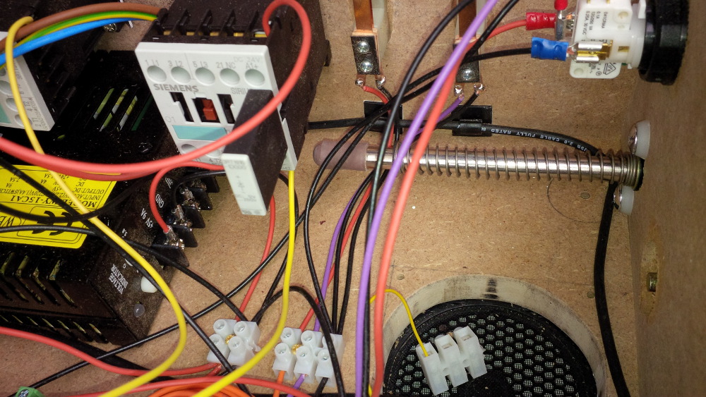
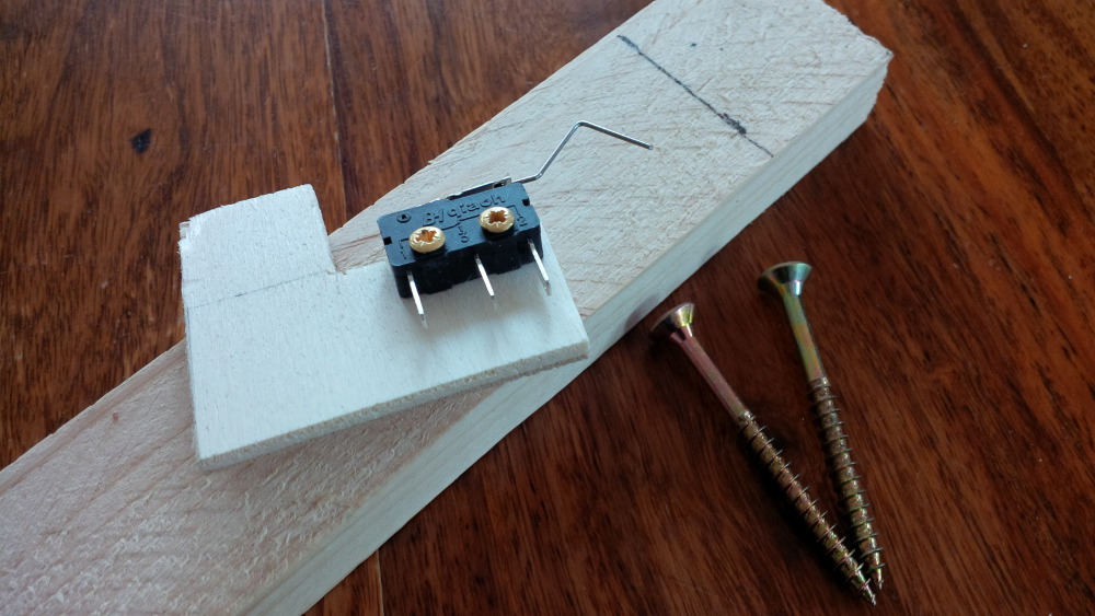
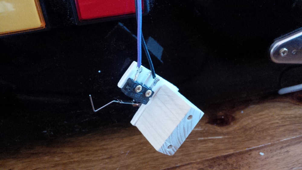
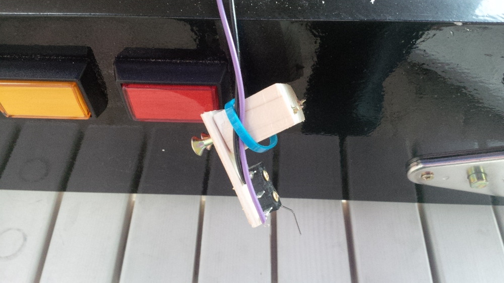
Ohhh yea, I really like this community. While I thought about wild ideas how to get a reliable and simple plunger setup I got a couple of great answers. Did you ever heard something about a "Tubular Inductive Proximity Sensor Approach Switch"? Hehe, yea... sounds like ninja or rocket science.  But it's a serios plunger switch solution. But the most genius idea came from BigBoss, thank you so much... It's so simple... I could simply mount my switch perpendicular instead of slamming directly into my switch and instead of creating a more creative solution. Could it be so simple? I tried it asap...
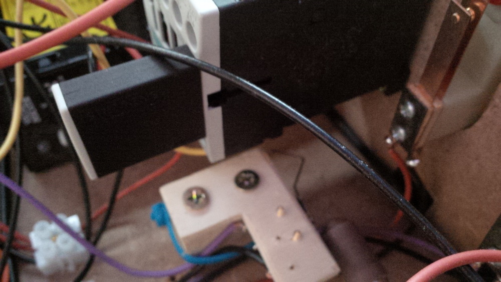
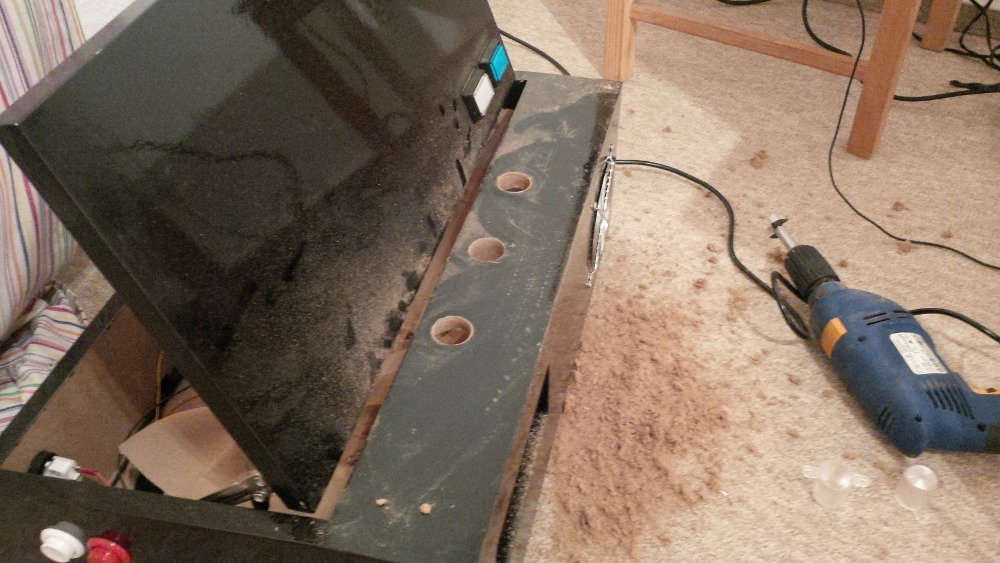
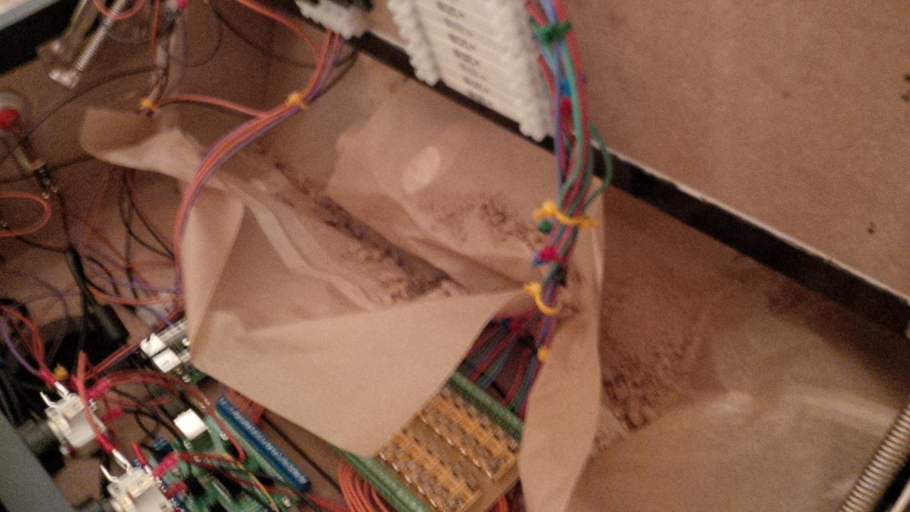
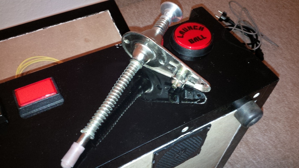
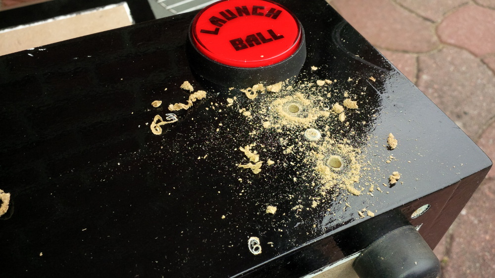
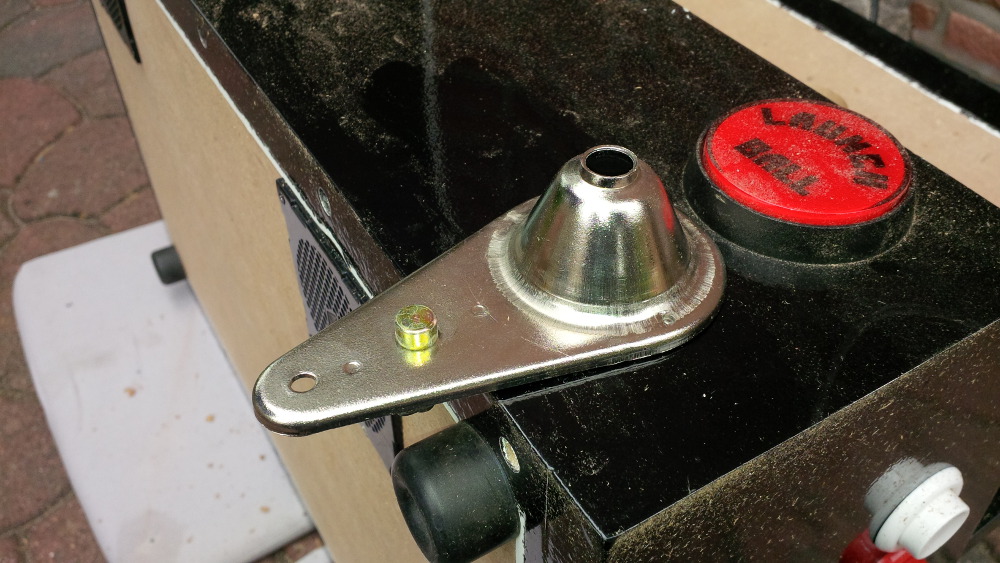
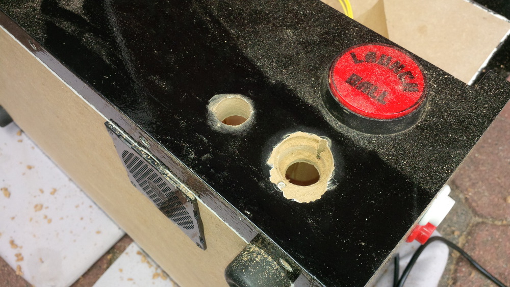
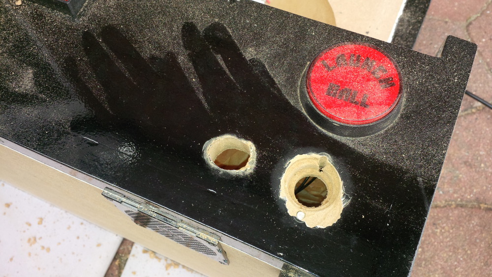
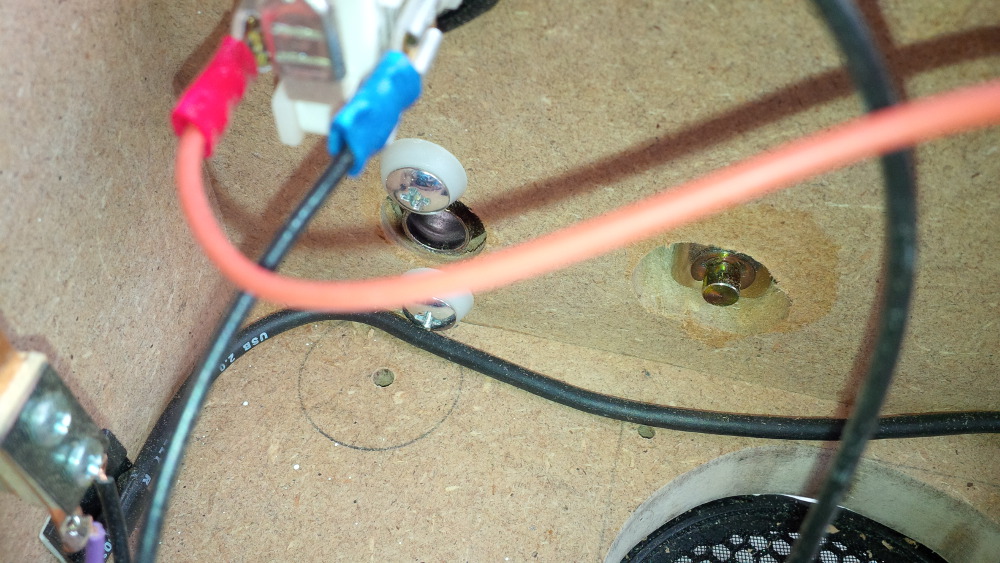
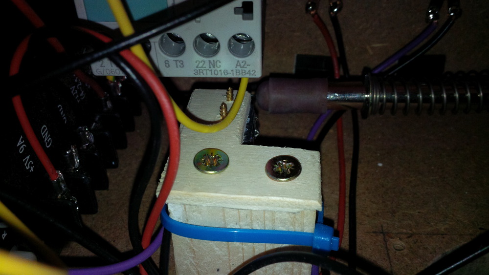
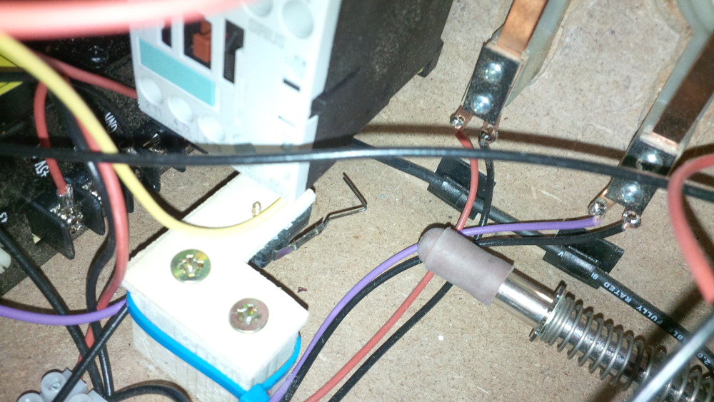
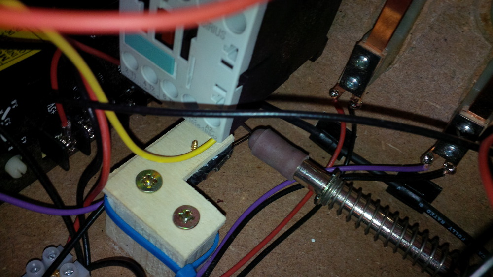
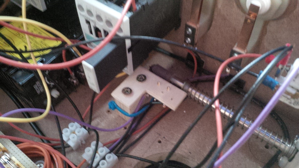
Firstly demounting my current switch assembly...
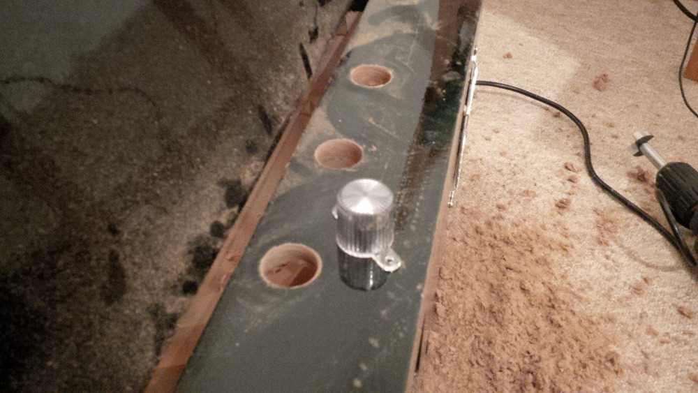
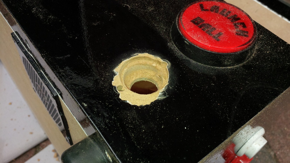
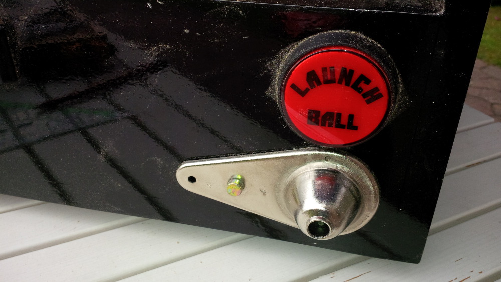
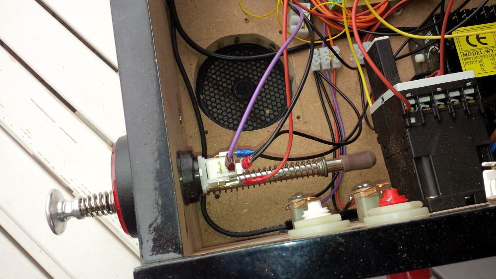
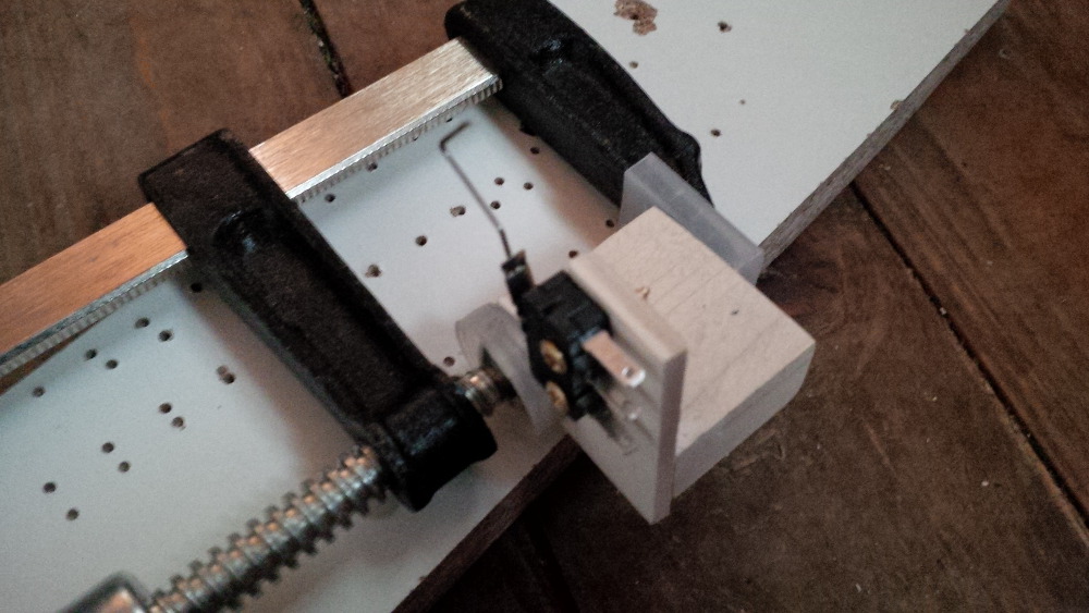
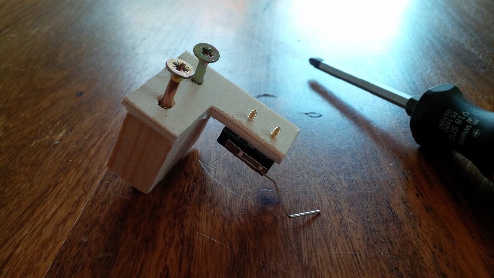
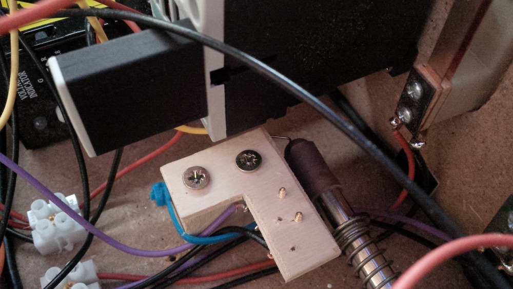
I had to re-adjust the assembly a bit and remounted it perpendicular.
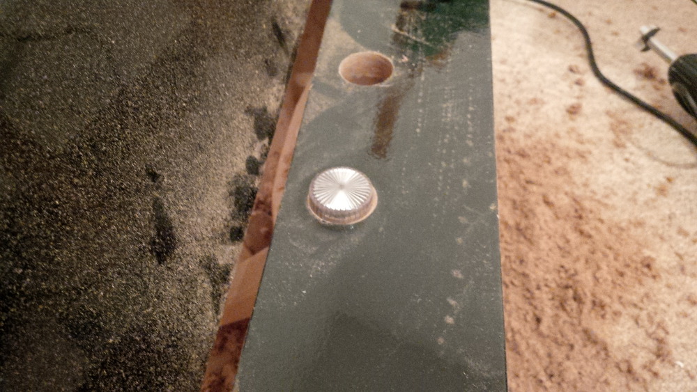
And it works like a charm! Yipee!
Pull...
...and SLAM... BAAAAAM... and again and again!
Fantastic - my plunger is working!
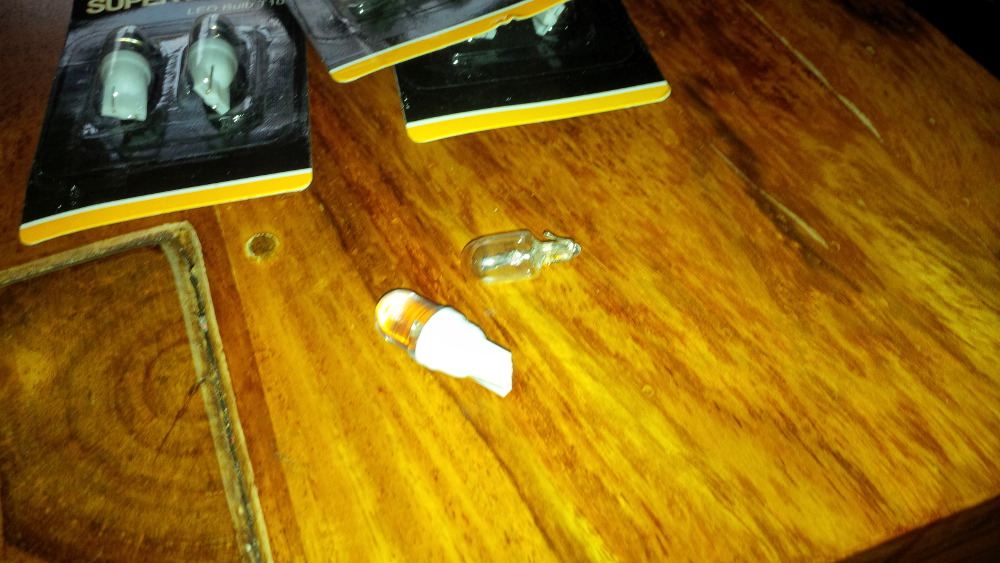
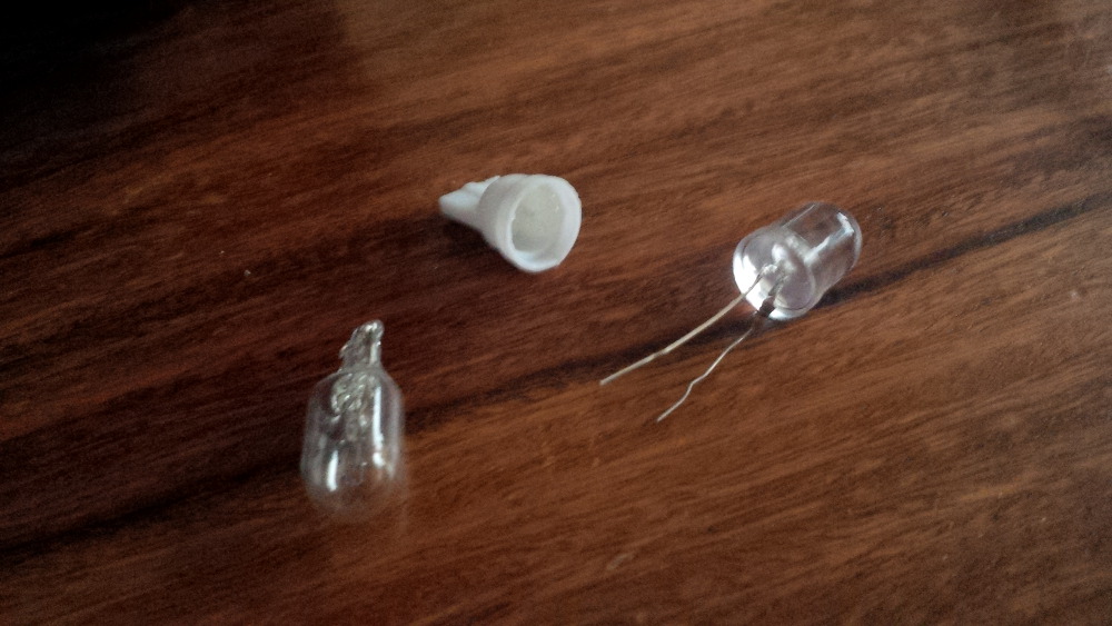
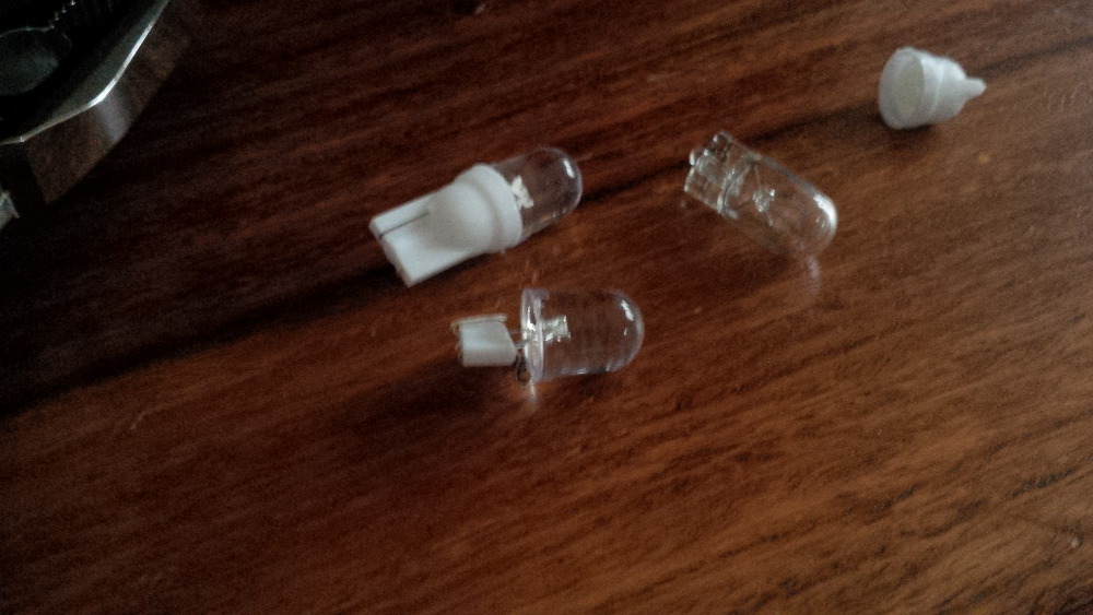
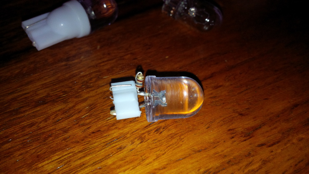
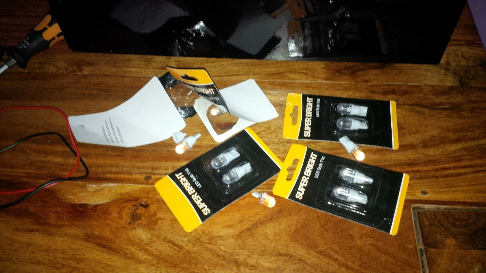
Coming soon: Chapter 20 - A disappointing bulb replacement
Edited by rasm, 02 June 2014 - 08:53 PM.
Visit my build: Yet another build thread
Enthusiast
Posted 02 June 2014 - 10:12 PM
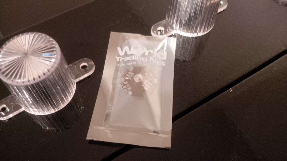
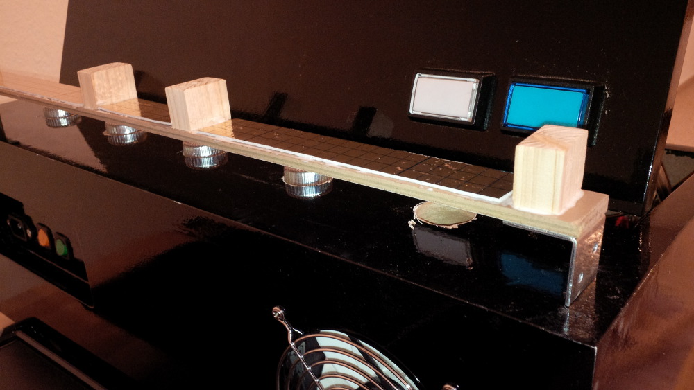
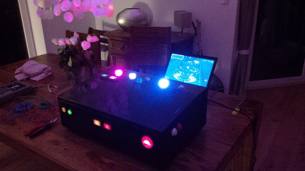
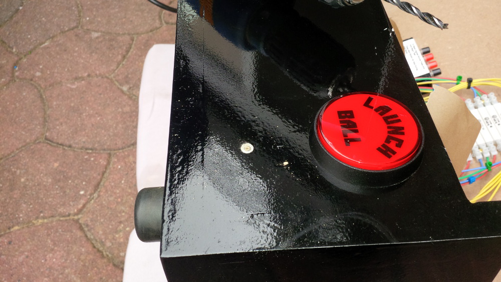
 . Addionally I hoped to get a brighter lightning, because my buttons looks very smooth like candle light. I paid only 1 Euro + shipping for a set of 10 LEDs - lucky.
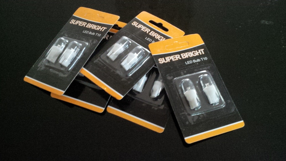


 I am fine.
Visit my build: Yet another build thread


Welcome to VPForums →
Pinball Discussion Forum →
Gameroom Discussion →
DIY vpin for 2025! The best options for playfield, PC, & more!Started by jdv , 23 Jun 2025 |
|
||
Visual Pinball Development →
Ideas & Suggestions →
Simple tables to implement for my toy simulatorStarted by lakmeer , 07 Jul 2023 |
|
||
Visual Pinball →
Animated Backglasses →
dB2S Animated Backglasses →
Tommy The Pinball Wizard (Data East 1994)_Wildman_Teisen(MOD) [dB2S]Started by teisen , 04 May 2022 |
|
||
Visual Pinball →
VP Help Center →
Tutorials →
DIY Chime Unit v1.0.zipStarted by bulldog4 , 25 Jan 2022 |
|
||
Visual Pinball Development →
General Chat →
Build a chime unit for under $40Started by bulldog4 , 25 Jan 2022 |
|

Community Forum Software by IP.Board
Licensed to: VPForums.org
 are all trademarks of VPFORUMS.