


2025 update - full guide can be found here.
This will walk you through setting up DOFLinx in all its modes with a reasonably straight forward configuration. I will avoid talking options on the way through. For options and custom setup, read the full guide that comes with DOFLinx, posts in the forums, and pose questions yourself as required.
Prerequisites to use all parts of this walk-through;
- Direct Output Framework Release 3++ installed and working
- Future Pinball installed and working
- Visual Pinball installed and working
- Pinball FX3 Steam version installed and working
- A LedWiz, Pinscape, PacLed64, Ultimate IO, PinControl 1, Pincontrol 2 or SainSmart device with toys
The configuration I will use is below. You should be able to search and replace to create your own setup.
(Sorry - haven't figured out how to get a table in here yet!)
Device LedWiz
Direct Output Framework folder C:\DirectOuput\
Location of directoutputconfig.ini file C:\DirectOutput\config\directoutputconfig.ini
DOFLinx download and unpack location C:\DirectOutput\DOFLinxDownoad\
INI file location C:\DirectOutput\DOFLinx_INI\
FX2 file location C:\DirectOutput\DOFLinx_FX2\
FX3 file location C:\DirectOutput\DOFLinx_FX3\
Location and name of Future Pinball C:\FP\Future Pinball.exe
Location and name of Visual Pinball 9.9.1 file C:\VP\VPinball_9_9_1.exe
Left Flipper key Left Shift
Right Flipper key Right Shift
Left flipper solenoid Device #1, port 17
Right flipper solenoid Device #1, port 25
RGB under cabinet lighting Device #1, port 9 (red port)
Left slingshot solenoid Device #1, port 18
Right slingshot solenoid Device #1, port 26
Mid field left solenoid Device #1, port 27
Mid field centre solenoid Device #1, port 28
Midfield right solenoid Device #1, port 29
Back left solenoid Device #1, port 30
Back centre solenoid Device #1, port 31
Back right solenoid Device #1, port 32
Shaker Device #1, port 15
Gear motor Device #1, port 16
Knocker Device #1, port 24
Strobe light Device #2, port 17
Beacon Device #2, port 18
Flasher - Outer left Device #2, port 1
Flasher - Inner left Device #2, port 4
Flasher - Centre Device #2, port 7
Flasher - Inner right Device #2, port 10
Flasher - Outer right Device #2, port 13
Start button LED Device #1, port 2
Extra ball button LED Device #1, port 1
Coin button LED Device #1, port 6
Exit button LED Device #1, port 4
This full configuration will:
- Provide simple force feedback for all Pinball FX2 & FX3 tables
- Provide full force feedback for Pinball FX2 & FX3 tables with memory mapped trigger files (FX2 and FX3 files)
- Connect to Future Pinball and provide full force feedback for Future Pinball DOFLinx coded tables
- Provide simple force feedback for Future Pinball tables not DOFLinx coded
- Provide simple force feedback for Visual Pinball (v9.9.1) tables flagged as having no built in force feedback
1. DOFLinx Installation
1.1 Download the latest version of the DOFLinx zip from VP Forums. Search “DOFLinx” in the downloads section.
1.2 Unpack the downloaded ZIP into C:\DirectOutput\DOFLinxDownload\ (note this folder is specifically just for unzipping, all files are copied or moved from here. You can elect to unzip directly into C:\DirectOutput if you want)
1.3 Unblock the EXE and DLL files
1.4 Copy C:\DirectOutput\DOFLinxDownload\DOFLinx.exe to C:\DirectOutput\
1.5 Copy C:\DirectOutput\DOFLinxDownload\DOFLinxExt.dll to C:\DirectOutput
1.6 Copy C:\DirectOutput\DOFLinxDownload\DOFLinxMsg.exe to C:\DirectOutput\
1.7 Add a DOFLinx shortcut to your start-up folder


1.8 Set the properties of the DOFLinx start-up shortcut to have “PATH_INI=C:\DirectOutput\DOFLinx_INI\” as a command line argument

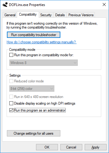
1.9 Set DOFLinx to run as an administrator (Note, from V7 onward this is now optional. DOFLinx can run without being set to run as admin - your choice)
1.10 Copy C:\Directoutput\DOFLinxDownload\FX2\*.* to C:\DirectOutput\DOFLinx_FX2\
1.11 Copy CL\Directoutput\DOFLinxDownoad\FX3\*.* to C:\Directoutput\DOFLinx_FX3\
1.12 Set up a configuration (INI) file by either;
a) Copy C:\DirectOutput\DOFLinxDownload\Sample INI FIles\DOFLinx.INI to C:\DIrectOutput\DOFLinx_INI\, or
b) Create and edit the file C:\DirectOutput\DOFLinx_INI\DOFLinx.INI
Note: You can comment out lines by making the first character a hash ( # )
Your C:\DIrectOutput\DOFLinx_INI\DOFLinx.INI should contain;
DIRECTOUTPUTCONFIG=c:\DirectOutput\config\directoutputconfig.ini
PROCESSES=Pinball FX2,Future Pinball,VPinball_9_9_1
L_FLIPPER_OUTPUT=117
R_FLIPPER_OUTPUT=125
L_FLIPPER_KEY=A0
R_FLIPPER_KEY=A1
MAX_FLIPPER_ON=5000
RGB_OUTPUT=109
RGB_STYLE=RANDOM
RGB_TRIGGER=FLIPPER
RGB_MIN_TIME=1000
PATH_FX2=C:\DirectOutput\DOFLinx_FX2\
PATH_FX3=C:\DirectOutput\DOFLinx_FX3\
2 Setup Future Pinball
2.1 If you do not have a C:\FP\Scripts\ folder then create one
2.2 Copy C:\DirectOutput\DOFLinxDownload\DOFLinx.vbs to C:\FP\Scripts\DofLinx.vbs
2.3 Add the following to your C:\DirectOutput\DOFLinx_INI\DOFLinx.INI
Change the device / port to the device / port that your devices are connect to.
If you do not have specific devices then simply delete the line, or add a hash # to the front of it to comment it out.
FP_ATTEMPT_LINK=1
LINK_LF=117,50,10000,255
LINK_RF=125,50,10000,255
LINK_LS=118,50,500,255
LINK_RS=126,50,500,255
LINK_ML=127,50,500,255
LINK_MC=128,50,500,255
LINK_MR=129,50,500,255
LINK_BL=130,50,500,255
LINK_BC=131,50,500,255
LINK_BR=132,50,500,255
LINK_SH=115,1000,5000,255
LINK_GR=116,750,10000,255
LINK_KN=124,120,500,255
LINK_SR=217,ON,0,255
LINK_BK=218,ON,0,255
LINK_FLOL=201
LINK_FLIL=204
LINK_FLCN=207
LINK_FLIR=210
LINK_FLOR=213
LINK_ST=102,MONO
LINK_EB=101,MONO
LINK_CN=106,MONO
LINK_EX=104,MONO
The devices that make up the XX in the LINK_XX above are;
LF = Left flipper
RF = Right flipper
LS = Left slingshot
RS= Right slingshot
ML = Mid field left solenoid
MC = Mid field centre solenoid
MR = Mid field right solenoid
BL = Back left solenoid
BC = Back centre solenoid
BR = Back right solenoid
SH = Shaker motor
GR = Gear motor
KN = Knocker
FN = Fan
FLOL = Flasher outer left
FLIL = Flasher Inner Left
FLCN = Flasher Centre
FLOR = Flasher Outer Right
FLIR = Flasher Inner Right
SR = Strobe
BK = Beacon
ST = Start button
EB = Extra Ball button
EX = Exit button
CN = Coin button
LB = Launch Ball button
FR = Fire Button
2.4 Install a Future Pinball table with DOFLinx code. You can search VP Forums and PinSimDB for DOFLinx enabled tables
3 Setup Pinball FX2 and FX3
3.1 Do nothing else (the LINK_xx) parameters in the Future Pinball section will take care of things), it is all setup!
4 Setup Visual Pinball (you only need to do this section if you are using, less than VPX tables, that don't have feedback coded and you want some)
4.1 Setup your front-end (ie PinballX) ‘Launch Before’ to message the TABLEFILE to DOFLinx, ie DOFLinxMsg GAME_FLAG_FILE=”[TABLEPATH]\[TABLEFILE]”

4.2 Setup your front-end (ie PinabllX) ‘Launch After’ to clear the GAME_FLAG_FILE to DOFLinx, ie DOFLinxMsg GAME_FLAG_FILE=
See the above image ‘Launch After’ section.
4.3 For the table that you want some flipper force feedback and RGB active for (TABLEFILE.vpt) copy C:\DirectOutput\DOFLinxDownload\SampleGameFlagFile.DOFLinx to C:\VP\Tables\TABLEFILE.DOFLinx
Note: TABLEFILE is the first part of the file name of the VP9 table, and if you use it B2S file
5 Follow-up
5.1 Backup your configuration
5.2 Read the full guide and see what other interesting stuff you can do to enhance your experience with DOFLinx
5.3 Keep an eye out for new tables, FX3 full force feedback configuration files and version updates
Edited by DDH69, 23 December 2025 - 11:32 PM.


 hehehe)


 are all trademarks of VPFORUMS.