


How to set up addressable LED strips for your cab
I spent many hours trying to get my addressable LED strips working so I put together this post to help save you the effort of trying to find all of the pieces of this puzzle and get them put together correctly!
Addressable LED strips can be used in many ways in a cab, the way that I’m going to describe is how to set up the strips that run up the sides of the cab that look like this:
If you want to set up the large matrix of LED in the back of the cab that can be used to replace 5 way flashers, look for TerryRed’s machine post to see how those are done.
You need three pieces of hardware to make addressable LED strips
-LED Strips
-Something to drive them
-Something to mount them on
LED strips are available from a wide variety of vendors and come in different LED densities ranging from 30 LEDs/m to 144 LEDs/m (WS2811/WS2812). The price goes up dramatically as you reach higher density LED strips but if you are making a matrix for the back of the machine density will determine resolution so I think higher is better. For my application I am making flashing, pulsing, strobing light effects for the side of the cab so I went with 60 LED/m strips. These strips are one directional in their signal flow and are marked with arrows to show that direction.

You can inject power and ground from any location in the strip but the signal must come from the starting end. Speaking of injecting power, these LEDs are power hungry so very long lengths or dense matrixes need power injected every 180 LEDs per one source. You can make longer chains as far as the data is concerned but power must be injected at least every 180 LEDs. These LED strips run on +5v and not the +12v that the under cabinet use.
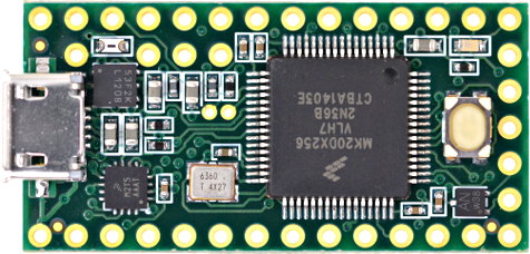
You next need something to control the LEDs, I chose to use the Teensy board to do this but you could use Arduino or another type of controller for this application. The Teensy board is available here and currently the 3.2 version is $19.80 so the price is reasonable
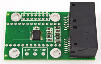
There is an optional daughter board that has two CAT6 cable connectors on it that can be used for easy data distribution OCTO2811 available here currently priced at $10
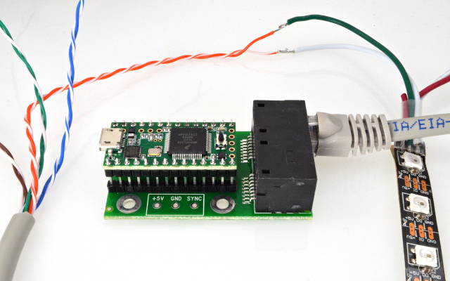
When these two are put together they look like this
The Teensy needs to be loaded with software to run the LED strips and the instructions for doing this are available here
The Teensy board connects up to your PC via USB cable so you need one of these with a regular USB on one end and a micro USB on the other.
The LED strips need +5v and Gnd to the outer two pads and assuming that you use the Octo28 adaptor you must connect a CAT6 cable to the strips to send the signal to them. As best I can tell Teensy sees the LED strips as one long continuous strip. This doesn’t mean that you have to daisy chain the strips together by sending the signal out the end of one strip and into the beginning of another. You can use up to 8 twisted pairs of wires from the CAT6 cables to send the signals to up to 8 different LED strips. The order of twisted pairs is:
Orange
Blue
Green
Brown
With the solid color being the data wire and the white being the ground. If your LED strips are like mine, they use black as ground and white as data so you need to hook up the colored CAT6 wire to white on the LED strip and the white CAT6 wire to the black on the LED strip. The jack on the right as you hold the jacks towards you sends the first four signals and the jack on the left handles signals 5-8.
The last thing that you need is some way to mount the LED strips in your cab. My play field TV has about 1/16” clearance on the sides so I had to either route a channel into the cab for these or make a removable strip to mount them on. Since my cab is assembled I mounted the LED strips onto a 1/16” think aluminum strip using Duck permanent double sided tape. This tape is made from white foam so it can insulate the bottom of the LED strips from the aluminum because the solder pads between each LED are not insulated on the bottom so shorting them out is a concern. I painted the aluminum strip and tape black for my cab.
The last part of the set up is getting DOF to talk to the Teensy controller. To do this you need a Global Configuration file and a cabinet configuration file in your Directoutput/Config folder.
Here is a copy of my Global Configuration file.
<?xml version="1.0" encoding="utf-8"?>
<!--Global configuration for the DirectOutput framework.-->
<!--Saved by DirectOutput Version 0.8.6002.28451: 2016-09-25 10-00-34-->
<GlobalConfig>
<LedWizDefaultMinCommandIntervalMs>1</LedWizDefaultMinCommandIntervalMs>
<LedControlMinimumEffectDurationMs>60</LedControlMinimumEffectDurationMs>
<LedControlMinimumRGBEffectDurationMs>120</LedControlMinimumRGBEffectDurationMs>
<IniFilesPath />
<ShapeDefintionFilePattern>{DllDir}\DirectOutputShapes.xml</ShapeDefintionFilePattern>
<CabinetConfigFilePattern>C:\DirectOutput\config\CabinetConfig.xml</CabinetConfigFilePattern>
<TableConfigFilePatterns />
<EnableLogging>true</EnableLogging>
<ClearLogOnSessionStart>false</ClearLogOnSessionStart>
<LogFilePattern>.\DirectOutput.log</LogFilePattern>
</GlobalConfig>
Here is a copy of my Cabinet configuration file this is the tricky one to set up because there is not a lot of information out there on how to do this. I'll inject notes in bold to explain what everything does. These bold notes should not be copied into the XML file or you will generate errors..
<?xml version="1.0" encoding="utf-8"?>
<!-- This config file will set up two addressable LED strips orange on the right and blue on the left. Each is 53 long and have the distal LED as the first in the array -->
<Cabinet xmlns:xsi="http://www.w3.org/20...chema-instance" xmlns:xsd="http://www.w3.org/2001/XMLSchema">
<Name>MultiBall</Name> Cabinet Name
<OutputControllers>
<TeensyStripController>
<Name>TeensyStripController</Name>
<NumberOfLedsStrip1>53</NumberOfLedsStrip1> Number of LEDs on the right playfield
<NumberOfLedsStrip2>53</NumberOfLedsStrip2> Number of LEDs on the left playfield
<NumberOfLedsStrip3>0</NumberOfLedsStrip3>
<NumberOfLedsStrip4>0</NumberOfLedsStrip4>
<NumberOfLedsStrip5>0</NumberOfLedsStrip5>
<NumberOfLedsStrip6>0</NumberOfLedsStrip6>
<NumberOfLedsStrip7>0</NumberOfLedsStrip7>
<NumberOfLedsStrip8>0</NumberOfLedsStrip8>
<ComPortName>COM3</ComPortName> You must look in device manager to see what port Windows assigned for the Teensy USB connection.
</TeensyStripController>
</OutputControllers>
<Toys>
<LedStrip>
<Name>PF Right</Name> This is the name that I gave the right playfield strip
<Width>1</Width> These strips run as one long string as far as the Teensy board is concerned. If you set the width to anything other than 1 it will give you funny results like the entire strip being LED 1
<Height>53</Height> This is the length of the right playfield LED array
<LedStripArrangement>TopDownLeftRight</LedStripArrangement> There are several choices that can be used here like BottomUpLeftRight. This determines the order of LEDs that the Teensy sends out on its signal path. If you use TopDown then the furthest LED from the connecting wires will be the first one in the segnal pathway. I needed this because I wanted my Teensy Board in the back of the machine by the power supplies to make the shorted wiring runs.
<ColorOrder>GRB</ColorOrder> You must choose GRB not RBG with these strips to get them to correctly display the colors sent to them
<FirstLedNumber>1</FirstLedNumber> This is the first strip so it starts with LED 1
<FadingCurveName>SwissLizardsLedCurve</FadingCurveName> I didn't play with this setting so I can't tell you what this does but I suspect that this sets the protocol that DOF uses for lighting the strips.
<OutputControllerName>TeensyStripController</OutputControllerName>
</LedStrip>
<LedStrip>
<Name>PF Left</Name> This strip is set up just like the other with exceptions in bold
<Width>1</Width>
<Height>53</Height>
<LedStripArrangement>TopDownLeftRight</LedStripArrangement>
<ColorOrder>GRB</ColorOrder>
<FirstLedNumber>54</FirstLedNumber> Since this is the second strip its first LED is the next one after the last LED on the other strip so since my strips are 53 LEDs long it is LED 54.
<FadingCurveName>SwissLizardsLedCurve</FadingCurveName>
<OutputControllerName>TeensyStripController</OutputControllerName>
</LedStrip>
<LedWizEquivalent>
<Name>LedWizEquivalent 30</Name> This is the number assigned to the WS2811 controller by the online DOF config tool
<Outputs>
<LedWizEquivalentOutput>
<OutputName>PF Right</OutputName> Name as defined above
<LedWizEquivalentOutputNumber>1</LedWizEquivalentOutputNumber> This is the port number of the first set of combos set up In the online DOF Config tool so it is port 1
</LedWizEquivalentOutput>
<LedWizEquivalentOutput>
<OutputName>PF Left</OutputName> Name as defined above
<LedWizEquivalentOutputNumber>4</LedWizEquivalentOutputNumber> This is the port number of the second set of combos set up in the online DOF config tool so it is port 4
</LedWizEquivalentOutput>
</Outputs>
<LedWizNumber>30</LedWizNumber>
</LedWizEquivalent>
</Toys>
<AutoConfigEnabled>true</AutoConfigEnabled> This needs to be set to true to work
</Cabinet>
The last thing that you need to do is to go to the online DOF config tool, sign in and make a new config file that includes a WS2811 controller. To do this you sign in and go to the My Account tab and increase the number of WS2811 Devices to 1 (for the Teensy board).
Next go to Combine Toys and make two combos one for the right PF Flashers MX and PF Effects MX and one for the left.
Lastly, go to the Port Assignments Tab, choose the WS2811 - directoutputconfigini30 device and assign port 1 to your first LED strip (1 red, 2 green, 3 blue) and port 4 for the second LED strip (4 red, 5 green, 6 blue).
You should now have everything you need to test out your strips and get them running!


 I do have some interesting bits of info though which might be interesting for others.


 ) - My


 are all trademarks of VPFORUMS.