
Jump to content


Photo
- - - - -

Tiki Gods Pinball cab 46"/32"/DMD Widebody Build


  • Please log in to reply
26 replies to this topic

#1 zeenon

zeenon

    Enthusiast

  • Platinum Supporter
  • 217 posts
  • Location:Somerville, NJ

  • Flag: United States of America

  • Favorite Pinball: Attack from Mars

Posted 29 July 2013 - 11:33 PM

I figure I would repost this on VPF since it is much easier to link to my build thread here.


- Cabinet

    Widebody based on the popular Williams plans by Mameman.
    Ultimate Cab-Builder's Kit (Widebody) ($400) LINK
    -----Optional Parts: (although these are not needed the header makes for a quick disconnect if needed, and the coin mech adds another touch of realism)
    -----13 Pin header for coin door ($1) LINK
    -----Happ coin door mechs ($20 total) eBay but here is a LINK
    Virtuapin Digital Plunger Kit ($140) LINK

    Paradise Arcade Clear IL Translucent button with Rollie Leaf switches for flippers ($5 ea)
    IL-lumination RGB LEDs for buttons ($2.75 ea)
    Bally Launch Ball button -Yellow ($10)
    Illuminated Reduced Footprint Pushbutton w/ Soft-touch switch (red,green,blue) ($2.25ea)
    LED-Wiz™ 32-port USB Lighting and Output Controller ($45)

    18 gauge wire (red, green, blue, black)

- PC Setup

    Windows 7 64-Bit
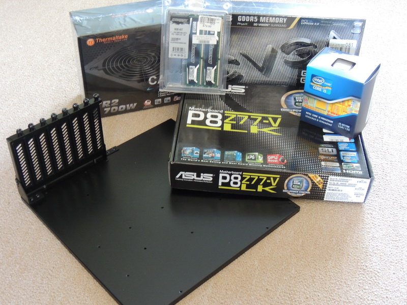
    Intel Core I5-3570K
    ASUS P8Z77-VLK ATX Motherboard
    Crucial 8GB 1600 RAM (2x 4GB sicks)
    EVGA GTX660SC 2GB PCIE Video Card
    Thermaltake TR2 700W ATX Power Supply
    Medialink Wireless Adapter ($20)

- Screens

    46" Playfield: Samsung UN46ES6003 Super Thin LED LCD 1080P ($640) Amazon Warehouse deals
    Decasing  here
    32" Backfield: Samsung UN32EH5000 1080p 60Hz LED HDTV ($280) Amazon Warehouse deals
    Vishay LEE-128G032B Orange LED DMD w/ PinDMD2 ($355)
    KK-156 (76650-0096) Molex connector for DMD ($3) LINK

- Sound

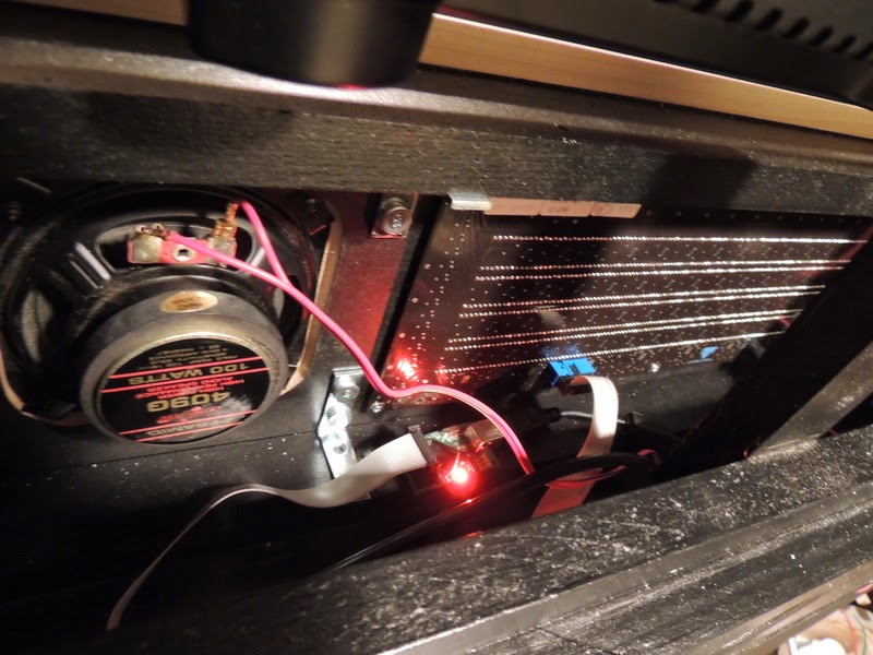
2 - Pyramid 4" dual cone 100W speakers #409G
Infinity 10" Subwoofer ($50)
Lepai LP-168HA 2.1 2x40W amplifier
Boss 400W 4 Channel Amp #CE404

- Lighting
- 5x Cree LED MCPCB STAR 3LED RD/GN/BLU ($12 ea) LINK
- 5x STARBOARD HEATSINK 2.88C/W 1" ($3 ea)LINK
- 2 x 22 LED white car Flash Strobe Emergency Light 12V ($14) LINK
- Arctic Silver Alumina AATA-5G Thermal Adhesive (for LED heatsinks) LINK


- Cooling

    5x Cooler Master 120mm R4 Computer Case Fan (R4-C2R-20AC-GP) $7.50ea Amazon
    5x 120mm chrome fan grills $3ea Amazon

- Misc Toys
    
    Zeb's Virtual Output Kit ($300) LINK
    Zeb's Shaker/Gear Motor Combo ($135) LINK
   Thermaltake TR-700 700W power supply for VOP ($)

    ATX Motherboard Tray - Black $32 Performance PCs
   Smart Strip LCG3 ($30)


Starting to get all the parts in:
DSCN0952_resize.JPG

Vishay and PinDMD2:
DSCN0968_resize.JPG

DSCN0970_resize.JPG

Custom made brackets made of angled aluminum to hold HD's. I may switch to SSD drive in the future.
DSCN0971_resize.JPG

46" Samsung playfield.
DSCN0972_resize.JPG

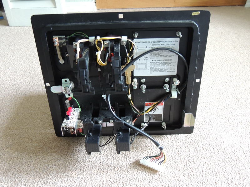
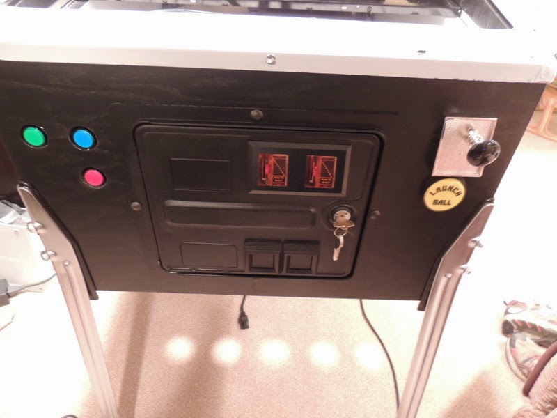
Coin door
DSCN0973_resize.JPG


DSCN0974_resize.JPG


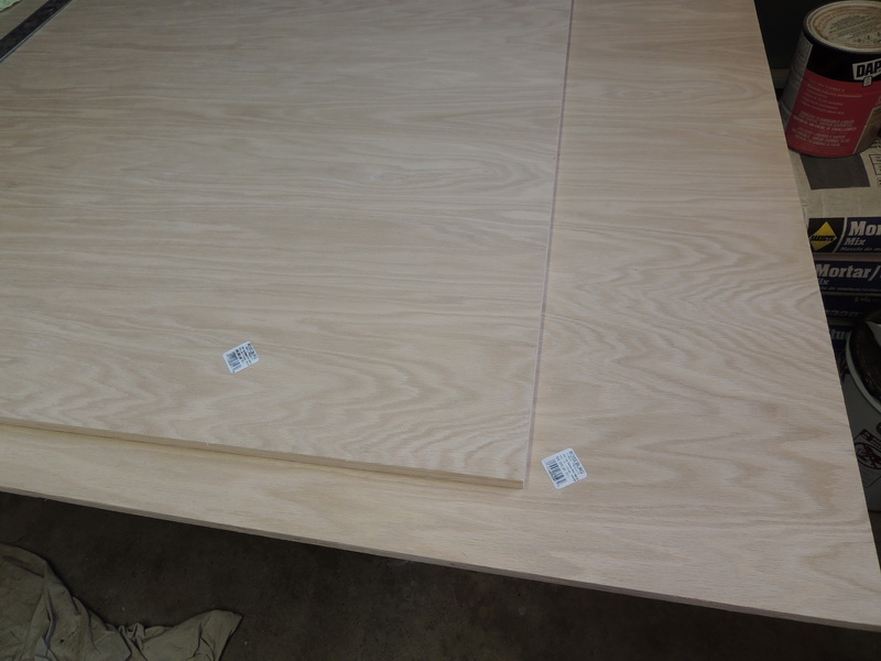
2 - sheets of 4x8 oak to start with:
DSCN0976_resize.JPG

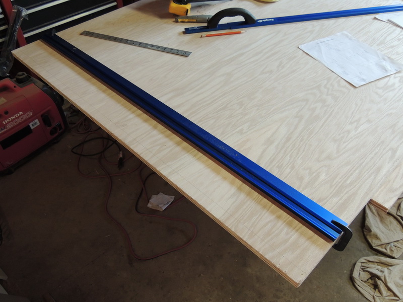
As seen on other posts I bought a set of metal guides since I was using a circular saw for 98% of the cuts:
DSCN0978_resize.JPG

First side cut:
DSCN0979_resize.JPG

Ahhh the finished product. I just wanted to see what I was dealing with so I dry fit all the pieces.
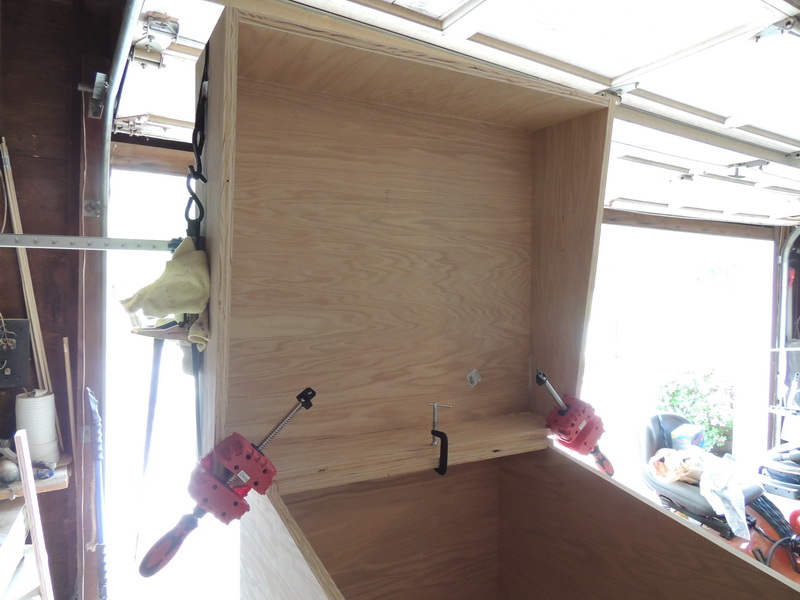
DSCN0982_resize.JPG

DSCN0983_resize.JPG


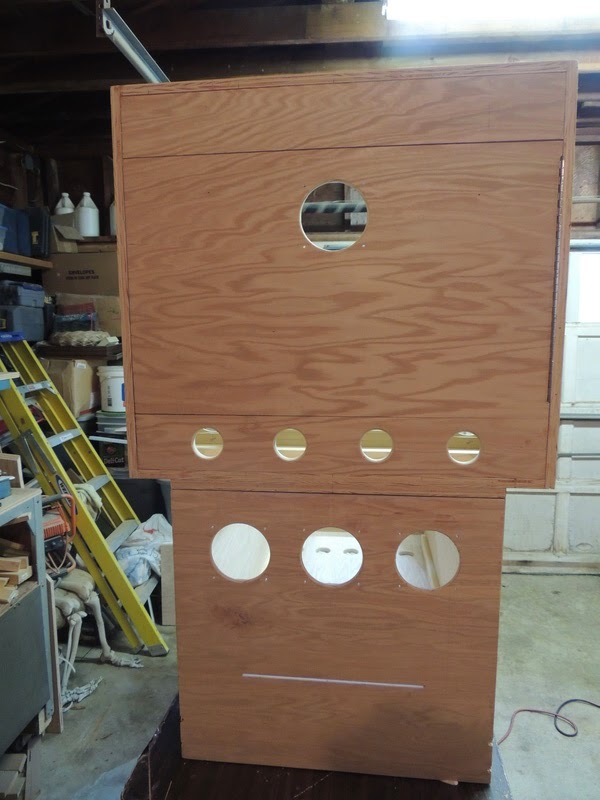
Cutting the holes in this cab was a breeze with scottpe advice on the circle jig (see scottpe Star Wars build). Never owned one before but it was invaluable.
DSCN0992_resize.JPG

Coin door. What a PITA, why are there notches on the left side....anyway.....used a jigsaw to rough cut then routed around for a clean line.
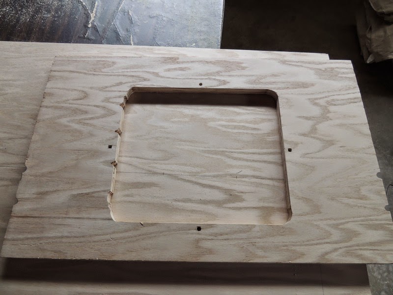
DSCN0993_resize.JPG

I used this router bit to make the holes for the leg bolts after hearing the pains everyone was experiencing (before gluing the cab together):
DSCN0994_resize.JPG  

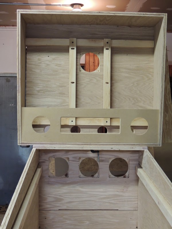
I bought a biscuit joiner during my MAME project so I figured I would bypass most of the screws and use biscuits and gorilla glue:
DSCN0995_resize.JPG  

For added strength (although the biscuits and glue were solid) I tacked down some 1" x 2" with screws on the bottom left/right:
DSCN1007_resize.JPG  

DMD panel
DSCN1017_resize.JPG

DSCN1013_resize.JPG

The speaker looks like it's not centered in this pic, but it is. The film is also still on the plexi.
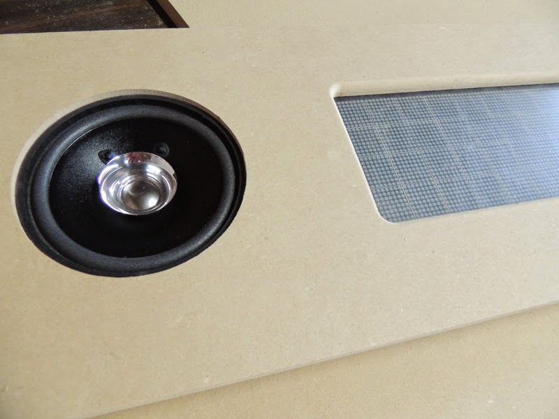
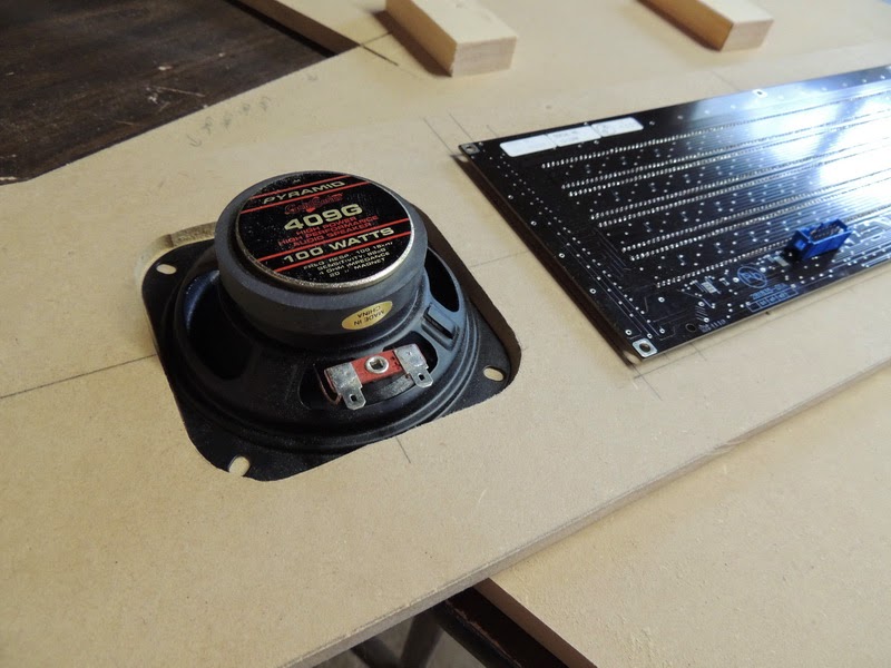
DSCN1015_resize.JPG


DSCN1016_resize.JPG

I have to say, scottpe's build is a great tutorial for those wanted to build a cab. (notice any similarities?) Between scott's and bill55 builds you have a ton of build pics. (BTW Scott we need more pics, I'm almost finished with the first chapter :) )
DSCN1018_resize.JPG


DSCN1019_resize.JPG

Couple spots here and there I touched up with Bondo.
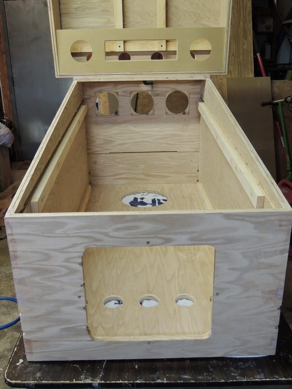
DSCN1020_resize.JPG


Edited by zeenon, 29 July 2013 - 11:33 PM.


#2 zeenon

zeenon

    Enthusiast

  • Platinum Supporter
  • 217 posts
  • Location:Somerville, NJ

  • Flag: United States of America

  • Favorite Pinball: Attack from Mars

Posted 30 July 2013 - 12:11 AM

Write up pending...............

Flipper placement: 3 1/8" from front edge, 2 5/16" down, 1 3/4" center to center.

DSCN1111_resize.JPG

DSCN1112_resize.JPG

DSCN1113_resize.JPG

DSCN1114_resize.JPG

DSCN1116_resize.JPG

DSCN1117_resize.JPG

DSCN1118_resize.JPG

DSCN1119_resize.JPG

DSCN1121_resize.JPG

DSCN1123_resize.JPG


http://youtu.be/DDEc0vQG1Ps


Edited by zeenon, 30 July 2013 - 12:14 AM.


#3 djcpe

djcpe

    Enthusiast

  • Members
  • PipPipPip
  • 159 posts
  • Location:Ohio, USA

  • Flag: United States of America

  • Favorite Pinball: Metallica, Wizard of Oz, Star Trek

  • PS3 Gamer Tag: Escape4
  • 360 Gamer Tag: Escape4

Posted 30 July 2013 - 01:38 AM

Perfection! Great work!

#4 gamefixer

gamefixer

    Pinball Fan

  • Silver Supporter
  • 575 posts
  • Location:Prosper, Texas

  • Flag: United States of America

  • Favorite Pinball: BK2K

  • PS3 Gamer Tag: gamefixer
  • 360 Gamer Tag: gamefixer

Posted 30 July 2013 - 01:57 AM

Very nice! I think I used the same monitor in my playfield. I even did the same thing you did to support it.


#5 GeorgeT

GeorgeT

    Enthusiast

  • Members
  • PipPipPip
  • 76 posts
  • Favorite Pinball: Funhouse

Posted 30 July 2013 - 04:45 AM

sweet build.  sofa king jealous!


#6 mameman23

mameman23

    Pinball Fan

  • Silver Supporter
  • 506 posts
  • Location:Farmington Hills, MI

  • Flag: United Kingdom

  • Favorite Pinball: Dr Who, robocop

Posted 30 July 2013 - 10:40 AM

Nice work.


Sent from my iPhone using Tapatalk 2
PM me for any CNC needs.
Find me on Facebook....Xtreme Pinball
Doctor Who Cabinet Build Thread Here
Tron Cabinet Build Thread Here
Big Bang Bar Build Thread Here
Mameman's cnc fun

#7 nickbuol

nickbuol

    Enthusiast

  • Members
  • PipPipPip
  • 268 posts
  • Location:Marion, IA

  • Flag: United States of America

  • Favorite Pinball: Theatre of Magic

Posted 30 July 2013 - 12:53 PM

Wow.  One of the fastest builds ever.  Start to finish in 38 minutes via 2 posts. :tongue3:


Looks great.  Really great. So many nice builds on here, and this is one of them.  No strange dimensions, oddsized backbox, no funky playfield angle...  Nice.


#8 zeenon

zeenon

    Enthusiast

  • Platinum Supporter
  • 217 posts
  • Location:Somerville, NJ

  • Flag: United States of America

  • Favorite Pinball: Attack from Mars

Posted 31 July 2013 - 03:33 PM

Nick, actually only 30 minutes, I had to transfer the pics to my PC :D .


Thanks for the comments everyone. If anyone has any questions on my build(no matter how simple) please don't hesitate to post. If you would like to see a pic of a certain section for clarification just ask.


Z


#9 zamzam974

zamzam974

    Hobbyist

  • Members
  • PipPip
  • 14 posts
  • Location:TACOMA, WA

  • Flag: France

  • Favorite Pinball: monster bash

Posted 04 August 2013 - 12:16 AM

hey zeenon,

nice build and look very clean. would you mind posting a few pics of your virtual output kit wiring with a few explanation if possible?

so that I can get in the right direction on mine.

thank you


#10 zeenon

zeenon

    Enthusiast

  • Platinum Supporter
  • 217 posts
  • Location:Somerville, NJ

  • Flag: United States of America

  • Favorite Pinball: Attack from Mars

Posted 04 August 2013 - 09:42 PM

zamzam,


Hopefully these will help :) little hard to fit a camera in a tight space.


DSCN1607.JPG


So first things first, on both boards (PWM and the Motor/Inductor) you want to use the 16 pin connectors closest to the upper left of each board labeled LEDWIZ INPUT. The Inductor board (top) gets wired to #1 to #16 on the LEDWIZ and the bottom (PWM) gets wired to #17 to #32. (The red striped wire goes to #1 (see pic) on the LEDWIZ, and the other one goes to #17). I missed out ;( Zeb now ships an LEDWIZ daughter board with the VOK which now you just wire the daughter board to the LEDWIZ and plug in the ribbon cables into the daughter board. (man this guy thinks of everything)


Top right of the picture is your standard PC power connector.


The next bank down is for your contactors. (Once I recoup from this project I may add them, but the bass and speakers provide ample force feedback)


The bank labeled EX, EB, LB, ST, and PWR are for your button lights on the front of your cab. I daisy chained the power to each button, then ran a single wire from EX,EB,LB,ST to the opposite light terminal of each button. Do not get these confused with the switch tabs (usually a microswitch) which are also on your button, those will be wired to your iPac or Virtuapin controller. Also make sure you select the proper voltage by selecting 12V or 5V on the POWER INPUT jumper. Mine is set to 12V.


Lastly, on this pic on the PWM board (bottom) if you have purchased Zebs Shaker and Gear combo the white wire is connected as shown. ****NOTE: DOUBLE CHECK the wire colors coming off the combo!!!!! I followed wiring directions on Zebs site and the depending on what wire was available at the time,  it may not be white.


DSCN1592.JPG


This is the other half, you can see the standard molex PC power on the top board, and the 20 Pin ATX power connector on the bottom. Note the power input connector on the bottom is not connected to anything.


On my High Power Output bank I have the Gear motor (heavy green wire) and strobe connected. For the strobe you toss the controller/battery box it comes with and attach directly to the Inductor board. (I needed to extend the wires but the red wire from each strobe is connected to the green and each black is connected to the white)


Lastly, your flasher outputs are on the bottom. Make sure you select the proper resistor bank depending on your CREE LEDS. Zeb has a pretty good diagram in the PWM Output Board instructions as to which output goes to which LED, but the way it is pictured above is the way you see it from the front of the cab......


Outside Left.....Inside Left.....Center.....Inside Right....Outside Right


DSCN1589.JPG


DSCN1595.JPG


I used two of these 12 pin connectors from RS as a quick disconnect in case I ever needed to remove the playfield.


DSCN1596.JPG


The CREEs/strobe wired.


DSCN1599.JPG


The lighting panel sits about a 1/16" above the playfield screen.


I'll add a pic of the LEDWIZ later tonight.


Z


Edited by zeenon, 04 August 2013 - 09:58 PM.


#11 zamzam974

zamzam974

    Hobbyist

  • Members
  • PipPip
  • 14 posts
  • Location:TACOMA, WA

  • Flag: France

  • Favorite Pinball: monster bash

Posted 05 August 2013 - 08:02 PM

thanks Z

those pics are a great help to me, I was confused about what it says on the board about grounding the ledwiz to board.

but sound like you don't need it.


#12 antropus

antropus

    Enthusiast

  • Platinum Supporter
  • 229 posts
  • Location:Bay Area

  • Flag: United States of America

  • Favorite Pinball: Monster Bash

Posted 05 August 2013 - 11:21 PM

Nice build! Looks pretty clean.

-Kris

#13 hogcia

hogcia

    Hobbyist

  • Members
  • PipPip
  • 22 posts
  • Location:New York

  • Flag: United States of America

  • Favorite Pinball: Super Mario Bros

Posted 07 August 2013 - 06:04 PM

Dam that's a nice build, wish I had the patience and time to build something like this. I am currently building a tabletop pinball machine. Hope to have it done soon. Nice job!

#14 zeenon

zeenon

    Enthusiast

  • Platinum Supporter
  • 217 posts
  • Location:Somerville, NJ

  • Flag: United States of America

  • Favorite Pinball: Attack from Mars

Posted 13 August 2013 - 11:26 PM

Used Clear 2"x4" mailing labels (Avery 5663) for my pin and mame cabs. Thanks to hogcia for the template!!!!


DSCN1619.JPG


DSCN1618.JPG


#15 Gamester

Gamester

    Enthusiast

  • Members
  • PipPipPip
  • 185 posts
  • Location:Texas

  • Flag: United States of America

  • Favorite Pinball: .

Posted 14 August 2013 - 06:20 PM

Really nice job zeenon.  Any plans for artwork, or are you going to stick with the black wood grain look?


#16 zeenon

zeenon

    Enthusiast

  • Platinum Supporter
  • 217 posts
  • Location:Somerville, NJ

  • Flag: United States of America

  • Favorite Pinball: Attack from Mars

Posted 14 August 2013 - 07:46 PM

:bar3:
Too busy enjoying the fruits of my labor!!!!


Honestly I haven't even thought about any artwork. I built the MAME cab first and just when I started the control panel I started the pin cab. So long story short I've been playing pinball (or loading new tables) for about 1-2 hrs a day for the last two months.


Z


#17 cmiller1

cmiller1

    Hobbyist

  • Members
  • PipPip
  • 22 posts

  • Flag: United States of America

  • Favorite Pinball: Goonies

Posted 21 August 2013 - 03:18 AM

What template or dimensions did you use to route out the square speaker hole in the DMD speaker panel?  I love that square look.


#18 zeenon

zeenon

    Enthusiast

  • Platinum Supporter
  • 217 posts
  • Location:Somerville, NJ

  • Flag: United States of America

  • Favorite Pinball: Attack from Mars

Posted 21 August 2013 - 05:11 AM

Are you talking about the DMD opening? If so, first thing I did was measure the DMD screen on my Vishay, and transfer that measurement to the panel. Note this measurement is only the viewable LED area plus 1/8". Next I used a router bit to cut out that square. I then used a round over router bit to round the front edge of the square. The reason for the 1/8" extra is because of the rounded inside corners. If you don't give yourself a little play, the LEDs on the corners will be cut off and hidden by the wood.

The rest is easy....now lay your DMD in the hole you just cut and trace around the PCB. Remove the DMD and take the distance from the DMD opening to the PCB and divide by two all the way around the backside of the DMD panel....this new square around your DMD opening is for your glass or plexi. Route that square out about 2x the thickness of your plexi. Drop your plexi in, then your DMD, and lastly screw the DMD down.

If its the speakers, I used a similar technique........cut round holes for the speakers, lay the speaker in the hole, draw the outline of the speaker. Route that square out (I wanted the speakers sunk into the wood). No need to round off the edges because the speaker grill hides the hole. Lastly, the speakers come with square grills that are just mounted to the front of the panel (no routing). The screws go into the grill, then the wood panel, the speaker, and then the supplied nut. So if your question is about the square speaker grills...they are just screwed into the panel.

Z

#19 cmiller1

cmiller1

    Hobbyist

  • Members
  • PipPip
  • 22 posts

  • Flag: United States of America

  • Favorite Pinball: Goonies

Posted 21 August 2013 - 07:52 PM

Thanks for both responses.  I was talking about the speakers.  Now that I took a close look at the speakers I see the square speaker and grille.


#20 gamefixer

gamefixer

    Pinball Fan

  • Silver Supporter
  • 575 posts
  • Location:Prosper, Texas

  • Flag: United States of America

  • Favorite Pinball: BK2K

  • PS3 Gamer Tag: gamefixer
  • 360 Gamer Tag: gamefixer

Posted 29 August 2013 - 03:32 PM

Hey Zeenon. I think you and I used the same monitor for the playfield. Have you noticed that the colors are washed out on some games? I'm also still seeing stuttering no matter how much I tweak things. Its driving me mad.