Jump to content


Photo
* * * * * 7 votes

Pinscape expansion board support thread


  • Please log in to reply
1103 replies to this topic

#801 MikePinball

MikePinball

    Oak Micros Pinball Products

  • Platinum Supporter
  • 416 posts

  • Flag: United States of America

  • Favorite Pinball: Space Invaders

Posted 04 November 2019 - 04:53 AM

Good find BorgDog but it kind of does the opposite of what we want. Interestingly it uses a microcontroller and a relay. I think this item is priced quite high for what is some basic electronics.


I think the idea I enumerated above has got be sufficiently interesting for me to prototype this idea. I outlined the logic in my previous append. The circuit board, microcontroller, relay and regulator should be no more than $20-25.


I will start a separate thread on this idea when I have made some more progress.


MikePinball (dba Oak Micros).


#802 dondi

dondi

    Enthusiast

  • Members
  • PipPipPip
  • 144 posts

  • Flag: United States of America

  • Favorite Pinball: Ace of Speed

Posted 04 November 2019 - 01:18 PM

I took my custom issue to a new thread here so as to not flood this here. Thanks for everyone's time and input. 


#803 duke atomic

duke atomic

    Hobbyist

  • Gold Supporter
  • 40 posts

  • Flag: ---------

  • Favorite Pinball: Flight 2000

Posted 29 November 2019 - 10:28 PM

Hi All, 


I'm a novice working out the kinks in a prototype mini-cab build.  I just received a Pinscape AIO from MikePinball and started diving into the Pinscape Config tool while the family was out Black Friday Shopping :)  


What's the secret for mapping the Enter key to a button??  


My setup is ultra-simple:  I do NOT have a plunger.  I just have a momentary push button that I want to map as the Enter key to push+hold to draw the plunger and release to launch... just like desktop VP.   I have chosen "No Plunger" in the Pinscape Config Tool. 


I don't have any outputs or DOF set up.  


I've got flipper buttons going no problem - super easy. Start button... no problem... So, I feel like I get the general principles for mapping buttons... but the darned Enter is driving me nuts.  


In Pinscape config tool has the Enter key defaulted to pin 11 on the expansion board... and I have it hooked up and common grounded with the rest of the buttons.  


#804 mjr

mjr

    Pinball Wizard

  • Members
  • PipPipPipPipPip
  • 3,331 posts

  • Flag: United States of America

  • Favorite Pinball: Medieval Madness

Posted 29 November 2019 - 10:38 PM

What's the secret for mapping the Enter key to a button??  


There shouldn't be any secret about it - just click the key cap in the button list and click on the Enter key on the little keyboard image that pops up.  Maybe if you could post a step-by-step of what you're doing, what's *actually* happening on-screen, and what you *think* should be happening at the stage where it goes wrong?  Remember that we can't see what you're doing from here (I'm still waiting for the government to give me access to that universal surveillance system!), so you have to walk us through it at the sub-atomic level, with each key press and mouse click and so on in excruciating detail.


#805 duke atomic

duke atomic

    Hobbyist

  • Gold Supporter
  • 40 posts

  • Flag: ---------

  • Favorite Pinball: Flight 2000

Posted 29 November 2019 - 11:04 PM

Hmm... So then it is pretty weird.  

I'm following the same process to map the flippers (Left and Right Shift keys) and Start (1 key):

Open the Config Tool...

Go to Settings...

Scroll down to Button Inputs... 

(I have not set a Shift button from the default of 0 (zero))

For each button I set:

     the Port:  Click on port and choose one of the pins from the list in the Main Board section (it shows a picture of a standard Pinscape Main Board... although I'm using the AIO I'm under the impression 1 is 1, 2 is 2, etc... 

     the PC Input: Click on the key cap icon and then press the intended button.  


I do that for my four buttons (two flippers, Start, and Enter) then hit Program KL25Z... wait for it to refresh... and then go to the Button Tester. 


In my list of buttons I have:

1     Button 1 (digital in)        key=1       Start Game

2 through 5 = not connected

6     Button 6 (digital in)        key=Enter    Plunger/Launch Ball

7-8 = not connected

9     Button 9 (digital in)        key = Shift Left       Left Flipper

10    Button 10 (digital in)     key = Shift Right     Right Flipper


Each button has its positive wire going to the corresponding input port on the AIO unit.  


But I get the same thing every time... Flippers and Start work flawlessly.  They test fine with the button test and work well in VPX.  But the Enter button is just "dead"... no action in Button Test or VPX. 


Things I've tried:

1. Checked the physical button:  I swapped it with a flipper button and there is no effect - the flipper still works but Enter does not.  I've also checked the button with a multimeter and it behaves as expected. 

2. Changed the Plunger/Launch Ball function in VPX to another key (I chose "P").  Then I re-mapped the button to the P key.  Oddly, this did not work either.  I ended up with a "dead" P button.  


I'm sure I'm doing something dumb... but I will take a break and look at it with fresh eyes in the morning.   


Thanks all!



#806 mjr

mjr

    Pinball Wizard

  • Members
  • PipPipPipPipPip
  • 3,331 posts

  • Flag: United States of America

  • Favorite Pinball: Medieval Madness

Posted 29 November 2019 - 11:18 PM

6     Button 6 (digital in)        key=Enter    Plunger/Launch Ball


This is such a common issue that it deserves a call-out topic in the Troubleshooting chapter.  It *does* have its own topic in the "Debugging the Expansion Boards" chapter, but since you're using the pre-built board, you (happily!) had no reason to look there.  Here's where to look for the quick answer:


http://mjrnet.org/pi...?sid=expanDebug


Look for "Some buttons are working, some aren't", and you'll have your answer. :)


[Edit] ...and I just added the topic to the Troubleshooting section as well.  Not sure how I missed that before, given how many times this has come up.


http://mjrnet.org/pi...troubleshooting


Edited by mjr, 29 November 2019 - 11:29 PM.


#807 duke atomic

duke atomic

    Hobbyist

  • Gold Supporter
  • 40 posts

  • Flag: ---------

  • Favorite Pinball: Flight 2000

Posted 30 November 2019 - 01:06 AM

Thanks mjr


Unfortunately, I'm still stumped (didn't I say I was going to put this down until tomorrow???)  


System Type is set to Expansion Boards (1 MOSFET, 1 Chime)


Continuity between the 6 header and PTC11 pin on KL25Z is good (although I see the note that this isn't the end-all-be-all test).  But that's a good sign.  


Here's where it gets creepy:  My flippers are working fine.  So, if I "take" one of those known good paths (expansion board header + KL25Z pin) and re-assign it to Enter/Plunger, it dies.  


I'll look it over again in the AM. 


Cheers


#808 mjr

mjr

    Pinball Wizard

  • Members
  • PipPipPipPipPip
  • 3,331 posts

  • Flag: United States of America

  • Favorite Pinball: Medieval Madness

Posted 30 November 2019 - 01:40 AM

duke atomic - very strange indeed.  So, you're saying that any button you map to Enter stops working in the button tester?  And button #6 works as long as you map it to some key other than Enter?  (Let's leave VP entirely out of this for now and just talk about the hardware connection as viewed in the button tester.)


#809 MikePinball

MikePinball

    Oak Micros Pinball Products

  • Platinum Supporter
  • 416 posts

  • Flag: United States of America

  • Favorite Pinball: Space Invaders

Posted 30 November 2019 - 04:12 AM

This is certainly unusual.


As MJR says, the key is problem isolation. Don't even start VPX. Just the Pinscape config tool and the button tester within. By connecting a button to any input connector, you will test both the button and that Pinscape has properly picked up the button presses and can issue the keyboard button press.


You can also separately start VPX and try pressing Enter on a keyboard and see if VPX crashes.


MikePinball (dba Oak Micros).


#810 duke atomic

duke atomic

    Hobbyist

  • Gold Supporter
  • 40 posts

  • Flag: ---------

  • Favorite Pinball: Flight 2000

Posted 30 November 2019 - 05:00 PM

Problem isolation indeed... We are fixed and the kids have been playing Medieval Madness all morning.  


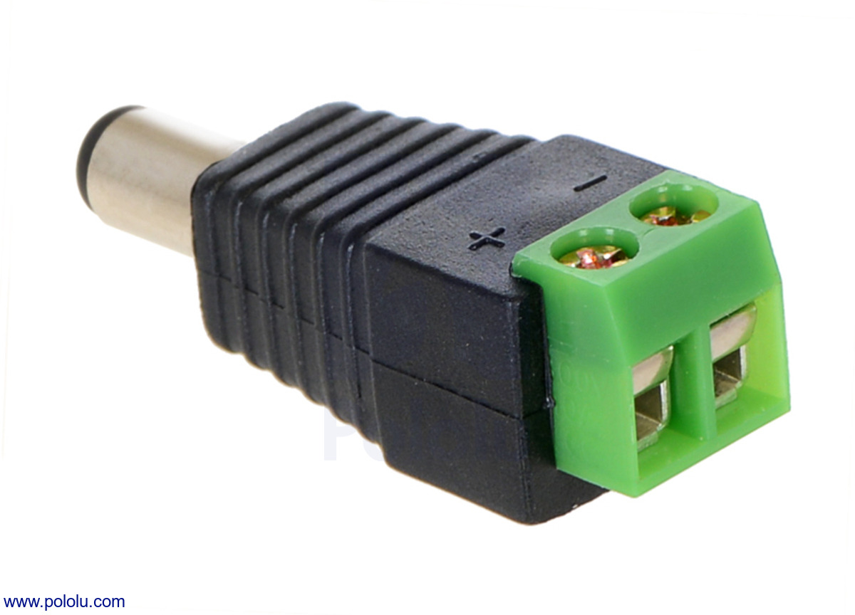
It0J4562.1200.jpg?ba21d81d9bc5f7e1c7fffb3f


It turned out to be one of these little buggers.  It was giving really wonky effects to the button.  Swapped out for a different one and all is well.  The irony is that I chose to use these to avoid problems like that :)   Ah well, a good lesson in double checking even the things you would least suspect.  


Thank you for the sanity checks!  


#811 dondi

dondi

    Enthusiast

  • Members
  • PipPipPip
  • 144 posts

  • Flag: United States of America

  • Favorite Pinball: Ace of Speed

Posted 30 November 2019 - 05:58 PM

It was giving really wonky effects to the button.  Swapped out for a different one and all is well. 

Out of curiousity @duke atomic, how did you have the DC Adapter wired between your launch button and the PinScape AIO? Were you using it for the LED?


#812 duke atomic

duke atomic

    Hobbyist

  • Gold Supporter
  • 40 posts

  • Flag: ---------

  • Favorite Pinball: Flight 2000

Posted 30 November 2019 - 09:23 PM

I was using these barrel connectors just to provide a convenient "break" in the wiring between the button (soldered wires) and the Pinscape AIO board (bare wire+screw terminal). I have male and female versions - one wires to the terminals of the button... the other to the Pinscape side.  Red wire (+) wire goes to the Pinscape AIO pin and the black (-) wire goes to a little homemade common ground bar (a row of screw terminals with all their pins soldered together). Just so I could quickly swap, test, etc.  This is is my first cabinet build and I'm just playing around to get the hang of everything before committing to a full build.  I could have used any connector (Molex, etc) but I had a pile of these in a drawer from another project (i'm big into Halloween and Christmas "villages" and these are useful to distribute power).  They're super convenient and I've never had a wonky one until now.  


Cheers


Edited by duke atomic, 30 November 2019 - 09:24 PM.


#813 MikePinball

MikePinball

    Oak Micros Pinball Products

  • Platinum Supporter
  • 416 posts

  • Flag: United States of America

  • Favorite Pinball: Space Invaders

Posted 30 November 2019 - 10:45 PM

Most buttons have spade connectors. I would get yourself the two different sizes you need for buttons and LEDs on buttons and crimp everything. That is physically secure but also allows you to detach stuff.

I don't understand the soldered wires. Perhaps a picture of the whole thing will help.

Anyhow I'm glad you got it all working and it was not Pinscape, the AIO board, or software.


Edited by MikePinball, 01 December 2019 - 06:23 AM.

MikePinball (dba Oak Micros).


#814 nevess

nevess

    Hobbyist

  • Members
  • PipPip
  • 49 posts

  • Flag: Portugal

  • Favorite Pinball: Indiana Jones

Posted 10 January 2020 - 03:48 PM

I have build the expansion boards and have the following problem, in the power board the output 16 of JP5 is always on. I have removed the following components but it does not make a difference:
- Q4D
- OK4
- IC1
 
What could this be?

Edited by nevess, 15 January 2020 - 08:07 AM.


#815 nevess

nevess

    Hobbyist

  • Members
  • PipPip
  • 49 posts

  • Flag: Portugal

  • Favorite Pinball: Indiana Jones

Posted 15 January 2020 - 08:07 AM


I have build the expansion boards and have the following problem, in the power board the output 16 of JP5 is always on. I have removed the following components but it does not make a difference:
- Q4D
- OK4
- IC1
 
What could this be?


I have done a couple more tests and I find out that only having power in the pc psu connector is enough to get the output always on.


#816 mjr

mjr

    Pinball Wizard

  • Members
  • PipPipPipPipPip
  • 3,331 posts

  • Flag: United States of America

  • Favorite Pinball: Medieval Madness

Posted 17 January 2020 - 01:44 AM

nevess - a couple of questions. 


First, when you say you tried removing the components, do you mean that you tested with no components installed, or that you tried replacing the listed parts with new components and tested with the new ones installed?  I'm guessing you mean you replaced the parts with new ones and tested with the board fully assembled again, but just want to make sure I'm understanding correctly.


Second, did you try reading through the troubleshooting procedures here?  http://mjrnet.org/pi...?sid=expanDebug


For an output that's stuck "on", I think these would be the most likely causes:


- Bad MOSFET.  Sounds like you've already tried replacing that, but are you sure the replacement part was good?  If it came from the same batch, maybe you had several bad ones.


- Short to ground on the MOSFET drain.  If you have the MOSFET out, you can try testing for continuity between the output pin (JP5 pin 16) and one of the ground pins on JP4. If there's continuity without the MOSFET in place, you must have a short somewhere - probably some stray solder connecting two pads somewhere.


If it's not one of those, then it's got to be further back in the circuit.  Check the solder connections for R27, and measure the resistance across R27 to make sure it's around 1000 ohms.  If you want to do a live test, check the voltage at the junction of R58 and R27 (adjacent to Q4D) relative to JP4 ground pins.  It should read 0V when the output is off and around 12V when the output is on.


#817 nevess

nevess

    Hobbyist

  • Members
  • PipPip
  • 49 posts

  • Flag: Portugal

  • Favorite Pinball: Indiana Jones

Posted 17 January 2020 - 08:27 AM

nevess - a couple of questions. 


First, when you say you tried removing the components, do you mean that you tested with no components installed, or that you tried replacing the listed parts with new components and tested with the new ones installed?  I'm guessing you mean you replaced the parts with new ones and tested with the board fully assembled again, but just want to make sure I'm understanding correctly.


Tested with no components installed.The only thing that I did not removed was the sockets for the IC1 and OK4


#818 mjr

mjr

    Pinball Wizard

  • Members
  • PipPipPipPipPip
  • 3,331 posts

  • Flag: United States of America

  • Favorite Pinball: Medieval Madness

Posted 17 January 2020 - 06:39 PM

Tested with no components installed.The only thing that I did not removed was the sockets for the IC1 and OK4


In that case, I'd say you must just have a simple short between the output pin and ground.  The output pin connects directly back to the MOSFET (Q4D) gate, so if the MOSFET were still installed, that could be the source of the short.  But without the MOSFET there, the only possible way the output could be on is for the output pin to be shorted directly to ground somewhere along that trace.  You should be able to test that by measuring the resistance between the output pin and the JP4 ground pins - it'll read as low resistance (zero ohms to a few ohms) if there's a short.  It should be reading "Infinity" (no continuity) if the port were working properly.


Assuming the short is there, my first guess would be a little bit of extra solder that's forming a short between the gate and source pads on Q4D.  It might be almost invisible to the eye, since the pads are close together and it could just be a little thin filament of solder forming the connection. You can try removing the solder with solder wick or a solder sucker and see if you can clear off enough of it to remove the short.  It's also possible that the board itself has a defect or damage that's creating the short somewhere along the trace.  If you can find that by visual inspection, you might be able to fix it by cutting the copper at the connection point with an X-Acto knife or something like that.


#819 nevess

nevess

    Hobbyist

  • Members
  • PipPip
  • 49 posts

  • Flag: Portugal

  • Favorite Pinball: Indiana Jones

Posted 17 January 2020 - 07:58 PM


In that case, I'd say you must just have a simple short between the output pin and ground.  The output pin connects directly back to the MOSFET (Q4D) gate, so if the MOSFET were still installed, that could be the source of the short.  But without the MOSFET there, the only possible way the output could be on is for the output pin to be shorted directly to ground somewhere along that trace.  You should be able to test that by measuring the resistance between the output pin and the JP4 ground pins - it'll read as low resistance (zero ohms to a few ohms) if there's a short.  It should be reading "Infinity" (no continuity) if the port were working properly.


Assuming the short is there, my first guess would be a little bit of extra solder that's forming a short between the gate and source pads on Q4D.  It might be almost invisible to the eye, since the pads are close together and it could just be a little thin filament of solder forming the connection. You can try removing the solder with solder wick or a solder sucker and see if you can clear off enough of it to remove the short.  It's also possible that the board itself has a defect or damage that's creating the short somewhere along the trace.  If you can find that by visual inspection, you might be able to fix it by cutting the copper at the connection point with an X-Acto knife or something like that.


I have done the test and i have no continuity between the ouput pin and JP4 ground pins.


I have done a couple more tests and I find out that only having power in the pc psu connector is enough to get the output always on.

This test has done with only with power in the JP1. What is wierd is that I have the the same test between the output pin and JP1 ground pin and there is continuity. According to the eagle schematic there are no traces to this ground. What am I missing?


#820 mjr

mjr

    Pinball Wizard

  • Members
  • PipPipPipPipPip
  • 3,331 posts

  • Flag: United States of America

  • Favorite Pinball: Medieval Madness

Posted 17 January 2020 - 08:26 PM


I have done a couple more tests and I find out that only having power in the pc psu connector is enough to get the output always on.


This test has done with only with power in the JP1. What is wierd is that I have the the same test between the output pin and JP1 ground pin and there is continuity. According to the eagle schematic there are no traces to this ground. What am I missing?


Correct - there should be no connection between the output pin and the JP1 ground pin.  So *that* must be the short circuit we've been looking for.  


Just to be sure we're on the same page here, this is the test:


* Remove Q4D entirely (nothing is in this slot in the circuit board now)

* Disconnect the output device from JP5 pin 16 (nothing is connected to this pin now)

* Disconnect all power plugs (JP1 and JP4)

* Using multimeter, measure continuity between JP5 pin 16 and JP1 ground pin -> CONTINUITY/zero ohms


Is that right?

If so, then you have a short somewhere between the output 16 pin and the JP1 ground pin.


One thing I'll add is that the JP1 ground pin is connected to the "signal ground plane", which is a big contiguous copper area that covers most of the unoccupied area of the board on the bottom side.  So check carefully around the JP5 pin 16 pad on the bottom.  Look for any sign that the solder on the pad is bridged to the "background" copper area surrounding the pin pad.  It's even possible that the board has a manufacturing defect that left a small connection in the copper itself. 


If you do confirm the continuity test as described above, so you're pretty sure that there really is an unwanted short circuit here, you might try taking an X-Acto knife and carefully carving out a ring around the JP5-16 pin pad area on the bottom side of the board to try to cut it off from the surrounding copper.  Whether it's some leaked solder or some remnant copper from the manufacturing process, that might break the short and get it working properly.


(The trace you do want to leave intact from pin 16 to Q4D is on the top of the board, so it should be pretty safe to carve out a ring on the bottom side to try to isolate the pad from the ground plane.)


Edited by mjr, 17 January 2020 - 08:26 PM.