Jump to content


Photo
- - - - -

[HELP] Power-On with Single Button Push & No ATX Disk Controller Power


  • Please log in to reply
11 replies to this topic

#1 dondi

dondi

    Enthusiast

  • Members
  • PipPipPip
  • 144 posts

  • Flag: United States of America

  • Favorite Pinball: Ace of Speed

Posted 04 November 2019 - 01:16 PM

Continuation from the PinScape thread in order to not flood it with my custom issue (click the link to the left to get the initial backstory and my specific issue in just a few posts). Thanks to those taking their time helping me with this. Based on @MikePinball and @MJR's suggestions, I reworked a schematic:

relay.jpg

I am feeling better that I am able to flag possible issues beforehand with my proposed setup. But, at the same time could use the assists, as I'm quite unsure when it comes to the hard electric parts of things and don't want to blow my stuff up. 
Option A:  PC USB --> 5V to 12V Adjustable Step-Up Voltage Converter Cable --> DC 5.5mm Plug/Breakout Adapter -- 12V relay controlling Secondary Power    (Alternative to A)

Option B1: PC USB --> USB 5V-to-12V Step-Up Module --> 12V relay controlling Secondary Power        (B2 link, B3 link, B4 link, B5 link)

Option C1: PC USB --> USB 5V Breakout Cable --> 5V One Channel Relay --> [don't know if there needs to be something to step-up voltage here] --> 12V relay controlling Secondary Power   (C1 Alternative, 5-12V Input Relay)


Please check out the links if you can, and let me know if I am on the right path in regards to what I'm looking at, as I feel like I am sometimes half-understanding the components from the electrical side. 

@MikePinball The PC is an Ultra-Small Form Factor (probably as big as your AIO board and not much bigger than it's power brick. I've used these for work in interactive, realtime, 3D stuff). It has an Intel i7-9750H and a GTX 2070 in it believe it or not. Can be easily mounted on the side of cabinet with a very small footprint. I intend on getting a barebones and simply adding my RAM and SSDs.


@MJR yes, your suggestions make sense. I tried to translate them into the Option C variants above. Hopefully, I am on the right track.


Someone previously mentioned latent power via USB. I find that's the case, I would probably inject one of these USB Killas:
killa.jpg


Lastly, the Technical Director at a company I work with had mentioned a supply company that deals with this type of stuff (controlling switches and hardware with relays and software and such). But frankly when I get to the site, I am overwhelmed. There may be an off-the-shelf type of thing in their offerings, but it's a bit too much to decipher. Here is a link to the site. If anyone is inclined and motivated. Their tagline is "Control Anything... anywhere."

Sorry for the long post.. I'm wordy. And many thanks to those offering suggestions assistance and their time for me, my upcoming build and the community.


Edited by dondi, 04 November 2019 - 01:41 PM.


#2 MikePinball

MikePinball

    Oak Micros Pinball Products

  • Platinum Supporter
  • 416 posts

  • Flag: United States of America

  • Favorite Pinball: Space Invaders

Posted 04 November 2019 - 02:31 PM

You can drive the relay using 5V from a USB port if you use a different kind of solid state relay (SSR) such as the ones documented here. It looks like the heatsink is essential. I"m not sure if anyone else has experience of these. They are more convenient and cheaper than a contactor.


USBKilla has no active circuitry and only works on a USB 2.0 port. It looks like your PC only has 3.0 ports.


Edited by MikePinball, 04 November 2019 - 02:41 PM.

MikePinball (dba Oak Micros).


#3 mjr

mjr

    Pinball Wizard

  • Members
  • PipPipPipPipPip
  • 3,331 posts

  • Flag: United States of America

  • Favorite Pinball: Medieval Madness

Posted 04 November 2019 - 05:29 PM

dondi - unfortunately, that "USBKilla" looks like it would take you back to square one.  You can see from the traces on the board that what it's doing is bypassing the power wires on the USB connector from your PC, and replacing them with the power connectors from the disk connector.  It cuts off power to the device by supplying the device through the disk power connector rather than the USB power connector.  (The disk connectors are always switched off when the PC is in standby.)  


So what I mean by "back to square one" is that this would work great... *if* you had a disk power connector to work with!  But of course the whole problem is that you don't.


(And I can't help but be pedantic here and point out that the USBKilla is embarrassingly mislabeled.  Those four-pin PC disk power connectors aren't Molex connectors at all, although they're often mistaken for them, as seen here.  They're actually a type of connector made by AMP/TE Connectivity.  They do look a lot like Molex's "Standard .093" four-pin wire-to-wire connectors, though, which is where the confusion comes from.  But it's a harmful sort of confusion if you're trying to order something because the two types don't fit together.)


#4 dondi

dondi

    Enthusiast

  • Members
  • PipPipPip
  • 144 posts

  • Flag: United States of America

  • Favorite Pinball: Ace of Speed

Posted 04 November 2019 - 05:48 PM

Yeah, I keep going back to Arnoz' site looking at other stuff and keep forgetting that the USBKilla is a no-go. I threw it in at the tail of my post not remembering it needed constant power, which defeats everything I'm trying to do here. 

MikePinball's SSR suggestion looks promising. Basically, just use USB power to trip the 5V relay side, which then activates the AC side (wired directly to the secondary outlet). 

My hope is that the PC doesn't have constant power running through the USB. If this is the case, I am thinking one of 2 or 3 things:
-- Find a way to squelch the outgoing USB power (probably unlikely)
-- I am pretty sure the PC has an LED in the power button. Thinking a bit laterally here, but the LED power is 3.3V or 5V?? If I am going to bother tapping into the header for soft power anyway, can I simply replace the power header of my own serving both the soft-power switch as well as the LED and run that to the SSR? Seems the SSR is kind to low voltage. Again, I am no electronics guy, but is this something doable if it turns out there is constant power via USB on the PC and turning everything off becomes an issue?
-- Lastly, ummm, 2 buttons at the front of the cab in addition to the MAIN toggle at the rear; one soft-power button strictly for the PC and the other for everything else (fed by 5V sitting on the primary "live strip") connected to the SSR wired to the secondary? Probably a decent Plan B?


#5 mjr

mjr

    Pinball Wizard

  • Members
  • PipPipPipPipPip
  • 3,331 posts

  • Flag: United States of America

  • Favorite Pinball: Medieval Madness

Posted 04 November 2019 - 05:58 PM

> -- Find a way to squelch the outgoing USB power (probably unlikely)


You can try the "Power Management" tab in Device Manager ("Allow the computer to turn off this device to save power") on your USB Root Hub(s).   "Allow" makes it sound like it might or might not work depending on your hardware.


> Thinking a bit laterally here, but the LED power is 3.3V or 5V?


That's an interesting idea.  It'll be 5V if it's like a normal desktop motherboard, but this one seems pretty idiosyncratic, so who knows.  The thing is that the control circuit probably won't be set up to provide more current than a small LED requires, like 20mA or so, which won't be enough to switch a mechanical relay.  It might be enough for a solid-state relay, though - those are basically MOSFET switches so they shouldn't require any significant current to activate.


> Lastly, ummm, 2 buttons at the front of the cab


Yeah, I was starting to think your best bet might something like that, although I'd keep it even simpler and just use a hard switch for the secondary power.  Not the neatest solution, but simple and reliable.


#6 MikePinball

MikePinball

    Oak Micros Pinball Products

  • Platinum Supporter
  • 416 posts

  • Flag: United States of America

  • Favorite Pinball: Space Invaders

Posted 04 November 2019 - 06:31 PM

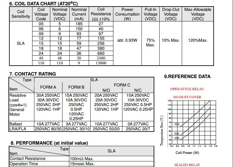
Did you take a look at the spec sheets for these Songle relays? I have one below. A USB port with the usual 100mA will not be able to supply enough current for the relay coil.


TB2SpsEdVXXXXcCXpXXXXXXXXXX-62505116.jpg


The SSR I noted above only needs 7.5mA @12V. 


I think the built-in buck/boost regulators built into the USB are overkill. Instead find a SSR that copes with 5V and you can connect to it directly. The second advantage is that a SSR has a built-in opto-isolator and doesn't need a diode like a relay coil. Here is a good overview of SSRs.


MikePinball (dba Oak Micros).


#7 MikePinball

MikePinball

    Oak Micros Pinball Products

  • Platinum Supporter
  • 416 posts

  • Flag: United States of America

  • Favorite Pinball: Space Invaders

Posted 05 November 2019 - 07:32 AM

To solve the power problems that Dondi and others have, I have created a Pincab power management circuit with all of the hard work done by a small Atmel microcontroller. The schematic is shown below. Here is a description of the operation:

  1. Connect "always on" power to the board using connector X2-2 and X2-3. An on-board buck regulator converts this to 5V and consumes very little current when everything is off. The maximum current needed is for the SSR or relay (say 200mA). The sources for this "always on" power can be the following:
    • The power brick (e.g. 19.5V) for a small form factor PC
    • The PC PSU +5V standby power (purple wire) output that is always on. It may be retrievable from the PC motherboard
    • A separate very small 5V power supply such as an old cell phone charger.
  2. Connect a power-on button to connector X2-1. A parallel on-board push-button is also provided for convenience. A momentary push of the button initiates the sequence to startup the PC. The microcontroller handles everything and can be in sleep mode until the button is pressed.
  3. When the button is pushed, the MOSFET is turned on and the corresponding LED is lit. The MOSFET output can be connected to a SSR or relay using connector X2-3 and X2-4. The SSR or relay is connects to a secondary power strip and is used to turn on all of the other hardware. Turning on this hardware first is preferred as it provides power to TVs, DMD, Teensy audio etc so that the PC can recognize the connections (USB etc).
  4. After a 5 second delay, the relay is turned on momentarily which can be used to turn on the PC and a main monitor/TV. You can connect the PC power on and a main monitor/TV on button to the two outputs from the relay (connections X2-5 through X2-8).
  5. The microcontroller monitors the USB connection and recognizes that the PC is on and turns on the corresponding LED.
  6. At some later time the user turns off the machine by pressing the button for 2 seconds. The relay pulses again which should initiate a PC shutdown and turns of the monitor/TV connected to the other relay output.
  7. Once the USB power disappears indicating that the PC as shutdown, the MOSFET is turned off which turns off the SSR/relay and the rest of the machine is powered off.

A bi-color LED could be used to indicate the status. Additional output pins could be used for a RGB or bi-color LED that is either in the power on button or separately installed on the coin door.


I haven't built or tried out this circuit yet so comments are welcome. I may have missed something important.


powermanagement.jpg


MikePinball (dba Oak Micros).


#8 dondi

dondi

    Enthusiast

  • Members
  • PipPipPip
  • 144 posts

  • Flag: United States of America

  • Favorite Pinball: Ace of Speed

Posted 05 November 2019 - 12:49 PM

C'est Magnifique @MikePinball! I see you have been busy with coming-up with a solution. What is great is that it looks like this can be a nice universal solution for the "One button, everything On" thing, where even those who have disk connectors and other available PC Power sources don't need to sacrifice a power rail in order to implement this solution (at least that is my interpretation of the above :-D).


What is also great, and something that was in my "mental wish list" that you already incorporated, was an LED status light indicator; I was thinking how I would use a simple on/off light for the momentary soft-power push button (I was going to tap-into the motherboard FPANEL header when I also grabbed the power).


Anyways, I have been reading and searching for the past day based on the feedback above (prior to the last post) and love this Solid State Relay. I think it's a clean and viable solution. But, as always in my travels, I get sucked down a rabbit hole...


ssr.jpg

...was wondering instead of that particular relay that is connected to a spliced Secondary Power strip, if this type of power strip (image below and linked) would work in it's place, based on MikePinball's latest solution — it looks like an addressable power strip with it's own relay incorporated into it. Looks like based on the schematic, one could wire outputs X2-3 and X2-4 into the relay portion of this fancy Relay Power Strip to power on "everything else" and not have to splice power strip cables.

psrelay.jpg


Again, thank you so much for your time everyone, and especially Mike and Mike. I hope my little issue here can turn into a nice solution, not just for me, but something easy, efficient and convenient for anyone looking to implement this method of powering-on their pinCab.


#9 MikePinball

MikePinball

    Oak Micros Pinball Products

  • Platinum Supporter
  • 416 posts

  • Flag: United States of America

  • Favorite Pinball: Space Invaders

Posted 05 November 2019 - 04:47 PM

A few comments:

  1. The 40A SSR is probably overkill and 20/25A is enough. I realize that this is the only one that Sparkfun lists but you can get them elsewhere. If I go ahead with my circuit, the plan is to include an SSR in the package.
  2. The DLI IOT relay you have shown above is limited to 12A which should be fine. There appears to be an internal opto-isolator which means that there is only a small curent draw and it should work fine with a USB port. BTW it is cheaper on Amazon than from the vendor. Two outputs is not enough so you will still need a secondary power strip as well.

MikePinball (dba Oak Micros).


#10 arnoz

arnoz

    Hobbyist

  • Members
  • PipPip
  • 14 posts
  • Location:France

  • Flag: France

  • Favorite Pinball: Monster Bash

Posted 10 November 2019 - 12:17 PM

Hello dudes !!!


I try to understand what is your problem (sorry, i'm a froggy so it's a bit hard to really understand all things ;) )


Simply, you want your Pincab computer to drive your second supply ?
And you can only use USB source because of your ZOTAC form factor...


my USBKILLA is'nt basically for you.
MJR has answer about it (Hey MJR, hello, and really, a huge thanks for your work !!!)


Anyway, i like to reverse my brain, and i think you can use my USBKILLA to powering a relay to drive your suply and other things....

You need to have an "USB OFF when PC is OFF" computer (i don't know the real name, but i think you understand my words....)

Just find an USB-A to USB-A cable and plug it into your PC and my USBKILLA OUTPUT, then, you will have 5V + GND on the MOLEX (https://www.molex.co...15244449_sd.pdf    ;) ) and also on the terminal bloc (easier) then you may drive a 5V relay board to drive your power supply.


Is that clear for you ?


And for my next design, i'll stop using technical references ;)

d2a8d3b7fd857a9a1eee8df8ed3efcdf.jpg


Edited by arnoz, 10 November 2019 - 04:25 PM.


#11 mjr

mjr

    Pinball Wizard

  • Members
  • PipPipPipPipPip
  • 3,331 posts

  • Flag: United States of America

  • Favorite Pinball: Medieval Madness

Posted 11 November 2019 - 12:23 AM

Dondi and MikePinball - I had another idea about how you could approach this, as long as you're thinking about having another microcontroller involved.  A microcontroller with a USB connection can tell whether Windows is up or not, even when USB power is still on, because Windows will stop responding to USB messages.  So you could come up with a little program for a Trinket or Teensy LC that would do nothing except send packets to Windows once a second or so, and if the writes fail, it would toggle a GPIO.  Use the GPIO to turn the relay on and off.  I'd put in a long delay on the ON->OFF transitions to make sure that you don't shut off the aux devices every time you reboot the PC or have momentary USB glitches - maybe leave AUX power on for 30-60 seconds after Windows looks to be down.


Pinscape could probably even do this with a little work, since it does keep track of the Windows connection state.


#12 MikePinball

MikePinball

    Oak Micros Pinball Products

  • Platinum Supporter
  • 416 posts

  • Flag: United States of America

  • Favorite Pinball: Space Invaders

Posted 11 November 2019 - 03:17 AM

Interesting idea MJR. I will have to think through the logic some more.


I was thinking of using an Atmel microcontroller. The ones with builtin USB would work well. An existing board like the Tricket might work for some people because they can easily add the custom electronics but for other users I would create a board from scratch that has all of the required functionality.


I like the idea of using the microcontroller as an intermediary between the cabinet (button and SSR) and the PC. The question is about what intelligence to apply and whether we need to go as far as a small PC front-end configurator for timeouts etc as well.


If you build the function into Pinscape then conceptually you could use the spare 4 GPIO pins to do work like firing the SSR or controlling a bi-color or RGB LED for status.


MikePinball (dba Oak Micros).