Jump to content


Photo
* * * * * 2 votes

Yet another build thread - getting things running

Pinball Wizard DIY Pinball Controls Small Box

  • Please log in to reply
71 replies to this topic

#61 rasm

rasm

    Enthusiast

  • Members
  • PipPipPip
  • 128 posts
  • Location:Hamburg

  • Flag: Germany

  • Favorite Pinball: currently Fish Tales

Posted 26 August 2015 - 09:49 PM

One year is gone…


Meanwhile I got my second wonderful and beautiful daughter and I took some time to arrange my life. Month by month - week by week it looks that I found back to a normal course of life, so that I think about next steps to continue my pinball adventure. 


But first things first. I want to post some progress from last year that was unpublished so far.


:coffee1:


Coming soon: Chapter 24 - Some cabinet makeup


Visit my build: Yet another build thread


#62 rasm

rasm

    Enthusiast

  • Members
  • PipPipPip
  • 128 posts
  • Location:Hamburg

  • Flag: Germany

  • Favorite Pinball: currently Fish Tales

Posted 26 August 2015 - 10:46 PM

Chapter 24 - Some cabinet makeup


Ohhh, I remember that it was the most precious week day: a Saturday!


Saturdays I am allowed to use noisy machines. On this morning unfortunately I saw a rainy cloud cover but I didn’t accept to wait again and again to try my new tool – the router.


chapter-24-01-routing-preparation.jpg


I was nervous like Free Willy before he jumps into the open sea when putting my new router on the 30 years old plywood.

My plan was to route a back door to the cab to push a TV from backside in later. To get an accurate route I spend some time in preparation and mounted a batten as supportive guidance.


Then I started the engine and I worked up a sweat when pushing down the routing drill. It’s important for a noob like me to find the right speed and right force when working with a cheap router.


A good thing is that I only know my cheap router, so I don’t miss a better one.


chapter-24-02-first-route.jpg


After my first route I was wiped out… and I was proud. The route looks fine for me.  :8):


I got a rainy refreshment and had to tidy up my stuff fasten – a short and exciting Saturday progress.


On the following Sunday I had to find a low noise way to get progress with my cabinet. So I inspected the cabinet surface and thought about how to fill all these big scratches, holes, gaps, damages and splintered corners. On the first look the cabinet is okay…


chapter-24-03-first-look.jpg


…but when taking a closer shot you see what I mean. The cab is definitely not in good shape.  :(


chapter-24-04-second-look.jpg


chapter-24-05-second-look.jpg


chapter-24-06-second-look.jpg


I used a spattle to grease some wood filler around the cab. Filigree to model corners! Always when I wanted to apply a last tender move like a breath as sensational finish I destroyed my passionate and accurate work. It’s obviously a better strategy to just ensure that enough filling paste is applied, so that I can finish the makeup later by a sanding it.


chapter-24-07-makeup-filling.jpg


chapter-24-08-makeup-filling.jpg


You know… I don’t own a grinder. I had to spend some hours to manually sandpaper the cab with my gentle hands.


chapter-24-09-makeup-sanding.jpg


chapter-24-10-makeup-sanding.jpg


chapter-24-11-makeup-sanding.jpg


The result is okay for now.


In my mind it was a bit strange to handle the knowledge about costs and long term estimation to finish this cab coupled with the up-growing idea that a newly built cab would be easier but for sure also less romantic, less magic. Will I ever finish this work? It’s so much easier and funny to make progress on my little box than on a real cab.


Visit my build: Yet another build thread


#63 rasm

rasm

    Enthusiast

  • Members
  • PipPipPip
  • 128 posts
  • Location:Hamburg

  • Flag: Germany

  • Favorite Pinball: currently Fish Tales

Posted 13 December 2015 - 11:09 PM

I put the Highspeed Cab in the garden house to forget it for a while. It's time for a new chapter with a playable outcome...

Chapter 25 - a shaker - "let's get ready to rumble"

This small and cheap piece of electronics is a so called Dual-H-Bridge.


chapter-25-00-dual-h-bridge.jpg


It's used to control electronical motors. In this case a fat expensive shaker to get my box ready to rumble. 

Ahhh yeeaaaa - a shaker is probably one of the cool parts. 


chapter-25-01-shaker-motor.jpg


I am really excited to feel the effect of this part... but... f*** - where to place this shaking monster in my box. Furthermore I am interessted in how to place it with my big fingers.

Here's an overview of the current status - or should I better say: current limits?!


chapter-19-22-overview.jpg


Okay, okay, I will stop moaning and start working.
 
First of all I was a bit afraid that my chaos setup as a mass of cables will easily get damaged by rotating shaker weights. So I decided to build a case to protect all my passionate work.
 
I planned a case as small as possible because, you know, space is very limited in my baby box. On the other hand it must be as big as needed, so that the shaker is able to work without destructing the case. For building the protection case I chose slim plywood and to train some more routing skills.
 
chapter-25-02-shaker-case-planning.jpg
 
From my first routing experience a lesson learned was to mount guidings to route as strong as possible. In this case I thought that the old backbox MDF plate could act as base plate and guiding rail and I simply screwed the plywood on top of it.
 
chapter-25-03-shaker-case-before-routing
 
Now it's time to dance with the router...
 
chapter-25-04-shaker-case-routing.jpg
 
Just after the first routes I started swearing. It's not easy to produce smooth routes I you don't have a smooth rail.
Yes, stupid!  :facepalm:
 
chapter-25-05-shaker-case-routing.jpg
 
So what... I need a functional protection case and not a trophy for accurate work.
 
chapter-25-06-shaker-case-parts.jpg
 
chapter-25-07-shaker-case-parts.jpg
 
chapter-25-08-shaker-case-parts.jpg
 
I routed all parts more or less in an adequate quality :-).
If you're thinking about something similar I would recommend to do it not in your basement. I produced a lot of dirt and had to arrange a special appointment with our vacuum cleaner. Ahhh, and it's really noise to route (with my cheap router). 
 
Then I started to glue all parts together. A liter of milk had a good weight to get close connections after drying.
 
chapter-25-09-glue-shaker-case.jpg


chapter-25-10-milk-on-shaker-case.jpg


This is the ready shaker case. Applause please!


chapter-25-11-ready-shaker-case.jpg


Edited by rasm, 13 December 2015 - 11:12 PM.

Visit my build: Yet another build thread


#64 vampirolatino2

vampirolatino2

    Pinball Fan

  • Members
  • PipPipPipPip
  • 1,430 posts

  • Flag: Spain

  • Favorite Pinball: Medieval Madness

Posted 14 December 2015 - 12:34 AM

Nice, the adventure continues!!! Yeah! :dblthumb:


#65 rasm

rasm

    Enthusiast

  • Members
  • PipPipPip
  • 128 posts
  • Location:Hamburg

  • Flag: Germany

  • Favorite Pinball: currently Fish Tales

Posted 14 December 2015 - 09:08 PM

It was a puzzle game like Tetris to find the right place to shake the box. In comparison the shaker is a relatively big component.
 
chapter-25-12-place-shaker-case.jpg
 
I need a small base plate as spacer to mount the shaker. Otherwise the weights would scratch the bottom of the box.
 
chapter-25-13-shaker-spacer.jpg
 
Hmmm, it's as it is: it's small and hard to mount things between the cables in my box. After mounting these shaker holders...
 
chapter-25-14-shaker-mounting.jpg
 
...it's done and the shaker arrived on his final position.
 
chapter-25-15-shaker-in-place.jpg
 
chapter-25-16-overview.jpg
 
I am sure, you will agree that it's danger to drive a shaker in this setup without any protection. So let's put the home grown case on top of it.
 
chapter-25-17-shaker-secured.jpg
 
chapter-25-18-shaker-secured.jpg

Visit my build: Yet another build thread


#66 rasm

rasm

    Enthusiast

  • Members
  • PipPipPip
  • 128 posts
  • Location:Hamburg

  • Flag: Germany

  • Favorite Pinball: currently Fish Tales

Posted 14 December 2015 - 10:51 PM

Soooooo...
 
...after all this wood building and mounting work it's time to put power on the shaker. To ensure a couple of effects produced by the shaker it must be controlled to run with different speeds (and maybe different directions, but not sure). It's not so much fun to simply put it on or off on full load. Any way to control different motor effects I will have to use a so called Dual-H-Bridge.
 
It will be connected with the shaker and the power line, sure. And to control it we'll setup a channel to the LEDwiz. You need a device capable to output PWM signals. Originally you would have to solder a wire on the SMD components on the LEDwiz. I skipped this and ordered a LEDwiz with this cable already soldered in place. If you followed my thread you know that I wouldn't be able to solder such fine connections - I would flood all SMD connectors with iron.  =@
 
Here you see the LEDwiz tuned with the yellow cable to allow PWM controlling for a motor driver like a Dual-H-Bridge.
 
chapter-15-09-ledwiz-cooling.jpg
 
Here's the bridge. I will mount it close to the LEDwiz, so that I ensure as much free space for bigger components as possible.
 
chapter-25-19-place-shaker-bridge.jpg
 
Keeping some free space - a very valuable good!
 
chapter-25-20-keep-free-space.jpg
 
As well as already setup for the contactors a diode is needed to protect sensible electronics against high capacitive load generated by the strong motor. I like to setup the diode without soldering directly on the contacts of a terminal block.
 
chapter-25-21-load-protection.jpg
 
chapter-25-22-load-protection.jpg
 
I wired a fresh 12V terminal block from the main supply. It was hard to deal screwing on the power supply bank behind the pregnant contactor.
Next time I should think about calling Mr. Fantastic and ask him how to stretch fingers.
 
chapter-25-23-new-power-terminal.jpg
 
chapter-25-24-new-power-terminal.jpg
 
You know that I don't own some of these nice connectors yet. So I soldered a cable directly to the input pin of the bridge.  :8):
 
chapter-25-25-shaker-bridge-setup.jpg
 
After putting everything in place the setup looks like this.
 
chapter-25-26-cabled-shaker-bridge.jpg
 
Ohhhhhhhhhhhh... testing time!
 
chapter-25-27-shaker-test.jpg
 
chapter-25-28-shaker-test.jpg
 
Yes! It's alive - it's rumbling!
 
chapter-25-29-shaker-is-working.jpg
 
But - wtf. Did I made a stupid mistake? I mounted the shaker directly next to the tilt pendulum?! Damn! That's definitely not a good idea, is it?
 
chapter-25-30-shaker-close-to-tilt.jpg
 
chapter-25-31-finished-shaker-work.jpg
 
Hmmm, but now it's mounted and I don't like to change it. So I decided to put a screen on the table and play an evening to test and adjust the shaker. 
 
Ladies and gentlemen, it works like a charm!
The shaker is in place. And it is rumbling the box without triggering tilt sensor signals. Puh - lucky!
 
chapter-25-32-enjoying-a-shaker.jpg
 
chapter-25-33-enjoying-a-shaker.jpg
 
chapter-25-34-enjoying-a-shaker.jpg
 
So this is the end of the shaker chapter. A big new component of my build.
The shaker produces very strong effects and it's fun to play all my tables with shaker support again to enjoy this new behavior. For me it feels not very natural but it boosts immersion to table's adventure in general. Nice shaking effects I tried e.g. on Attack from Mars, Medival Madness and Monster Bash.
 
Coming soon: a relay board and gear motor extension.  

Visit my build: Yet another build thread


#67 vampirolatino2

vampirolatino2

    Pinball Fan

  • Members
  • PipPipPipPip
  • 1,430 posts

  • Flag: Spain

  • Favorite Pinball: Medieval Madness

Posted 14 December 2015 - 11:00 PM

But, but, but .... now that you have a real cabinet, why don't you transfer all the stuff there?


#68 rasm

rasm

    Enthusiast

  • Members
  • PipPipPip
  • 128 posts
  • Location:Hamburg

  • Flag: Germany

  • Favorite Pinball: currently Fish Tales

Posted 15 December 2015 - 06:32 PM

But, but, but .... now that you have a real cabinet, why don't you transfer all the stuff there?

 
Ohhh... you're so right, vampirolatino2.
 
Currently the original cab is hidden behind some stuff in the garden house. 
 
fun-02-01-cab-in-corner.jpg
 
I've to accept that it's a bigger project. In the baby box I can add a new toy in just an evening or two after spending few bucks investment and I can directly play it.
 
But for sure, in my pinball heart is something growing and growing and the time will come to build a real cab.
 
What do you think? Should I canabalize the baby box and destroying it or should I buy a new set of parts?

Visit my build: Yet another build thread


#69 vampirolatino2

vampirolatino2

    Pinball Fan

  • Members
  • PipPipPipPip
  • 1,430 posts

  • Flag: Spain

  • Favorite Pinball: Medieval Madness

Posted 15 December 2015 - 06:51 PM

To be honest, reading about your new baby and to cut expenses, you should transfer all the things to the Cabinet. And put in that corner the old box. You have done all the "hard work" already. Just a full transfer of what you have in a "bigger scale", you will feel the difference when you start playing with the "real deal".


Cheers!


#70 rasm

rasm

    Enthusiast

  • Members
  • PipPipPip
  • 128 posts
  • Location:Hamburg

  • Flag: Germany

  • Favorite Pinball: currently Fish Tales

Posted 15 December 2015 - 07:07 PM

To be honest, reading about your new baby and to cut expenses, you should transfer all the things to the Cabinet. And put in that corner the old box. You have done all the "hard work" already. Just a full transfer of what you have in a "bigger scale", you will feel the difference when you start playing with the "real deal".


Thank you for kicking my ass.  :tup:

I will start again keeping my eyes open for a proper playfield TV.


Visit my build: Yet another build thread


#71 rasm

rasm

    Enthusiast

  • Members
  • PipPipPip
  • 128 posts
  • Location:Hamburg

  • Flag: Germany

  • Favorite Pinball: currently Fish Tales

Posted 15 December 2015 - 08:23 PM

Before pushing the "big thing" - a real cab - I will continue to show you some other toys that found the way into the controller box.
 
Chapter 26 - A relay board for more fancy toys
 
Some toys consume too much load to be controlled directly via a controller like the LEDwiz. To get them working a relay has to be placed in between, so that a low current circuit can switch a "higher power" on a secondary circuit.
 
For our convenience such relays can be ordered pre-mounted on a board. I chose a relatively cheap SainSmart relay board with 8 channels. This board allows to switch eight more toys like heavy solenoids or motors.
 
chapter-26-01-relay-board.jpg
 
Tipp: These relay boards are also available with an USB port to controll the channels. As far as I know this kind of board is already available in DOF, so that it can be used as inexpensive LEDwiz alternative.
 
Hehehe, you know... I am a bit sick when finding pins on boards and directly start soldering on them.
 
chapter-26-02-relay-board-soldering.jpg
 
Firstly I prepared the low current power circuit to let the realys working.  
 
chapter-26-03-relay-board-soldering.jpg
 
Make some noise for my soldering spots - it's a kind of art.  
 
chapter-26-04-relay-board-soldering.jpg
 
Here I connected a cable to switch the first relay (pin 1).
 
chapter-26-05-relay-board-soldering.jpg
 
And the final artwork.  :hi:
 
chapter-26-06-relay-board-soldering-artw
 
A central place to switch toys all around the box (probably close to the left free space) is on the top plate, next to the service buttons.
 
chapter-26-07-relay-board-mounting.jpg
 
After mounting the board and the related terminal block I had to connect the power for the board. I simply attached the board to the 5V circuit of the lamps by hacking into the existing daisy chain.
 
chapter-26-08-relay-board-wiring.jpg
 
The yellow wire has to be connected with a LEDwiz output to control the first relay. I still have enough free ports on it.  
 
chapter-26-09-relay-board-wiring.jpg
 
In between the connection passes my fuse board.
 
chapter-26-10-relay-board-wiring.jpg
 
And it's done! The realy board is connected.
 
chapter-26-11-relay-board-wiring.jpg
 
Time for the test. Fortunately it worked directly and I switched the first relay smoothly on and off via the LEDwiz. 
 
chapter-26-12-relay-board-testing.jpg
 
chapter-26-13-relay-board-testing.jpg
 
Yeaaaaah - it makes a sound when switching the realy - it's so cool to see things working.  :nunchacku: 
 
But... I will have some more fun with this board in the next chapter when I tried to connect a consumer and didn't understand the order of of relay connections. Stay tuned!

Edited by rasm, 15 December 2015 - 08:24 PM.

Visit my build: Yet another build thread


#72 rasm

rasm

    Enthusiast

  • Members
  • PipPipPip
  • 128 posts
  • Location:Hamburg

  • Flag: Germany

  • Favorite Pinball: currently Fish Tales

Posted 15 December 2015 - 10:19 PM

Chapter 27 - A gear motor and a bumper surprise
 
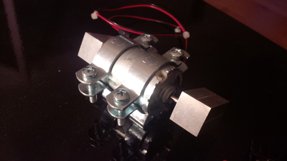
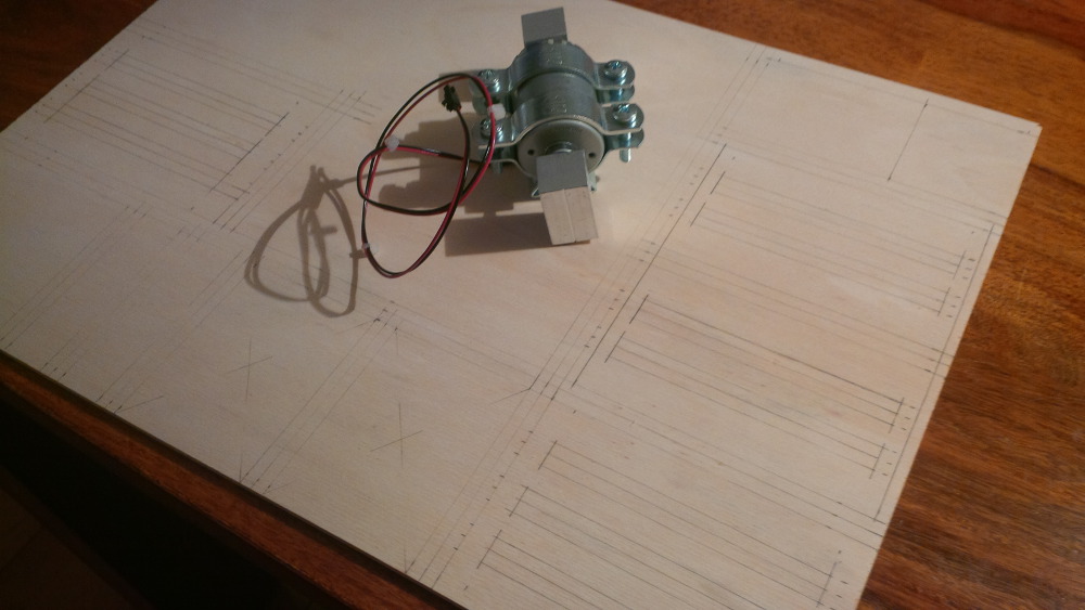
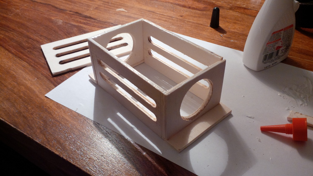
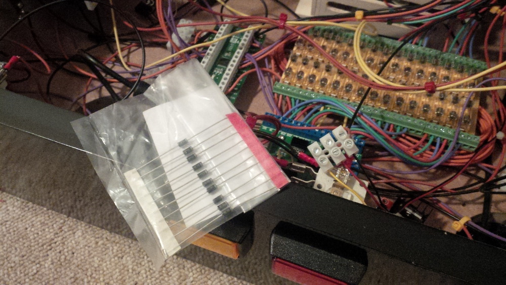
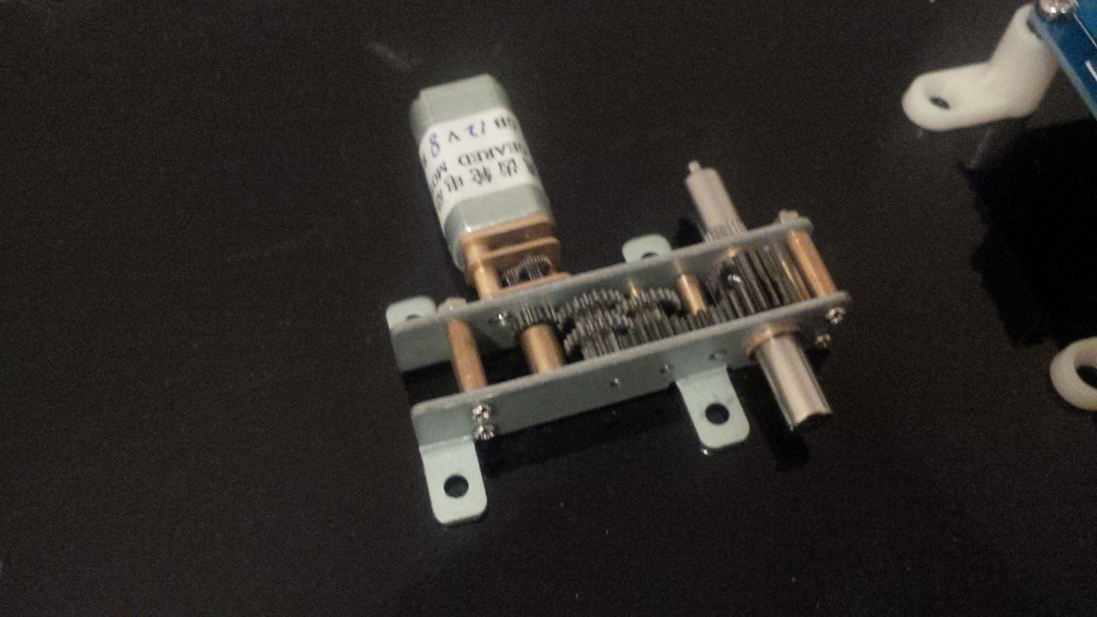
I got a very cheap gear motor from China that I saw in some other build threads here.
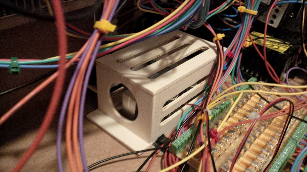
A gear motor shall create a real gear sound "bssssssssssssssss" when mechanical parts are moved on the table. It is looking really cool from my personal perspective.
 
chapter-27-01-gear-motor.jpg
 
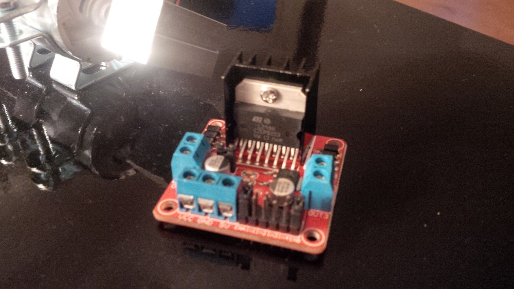
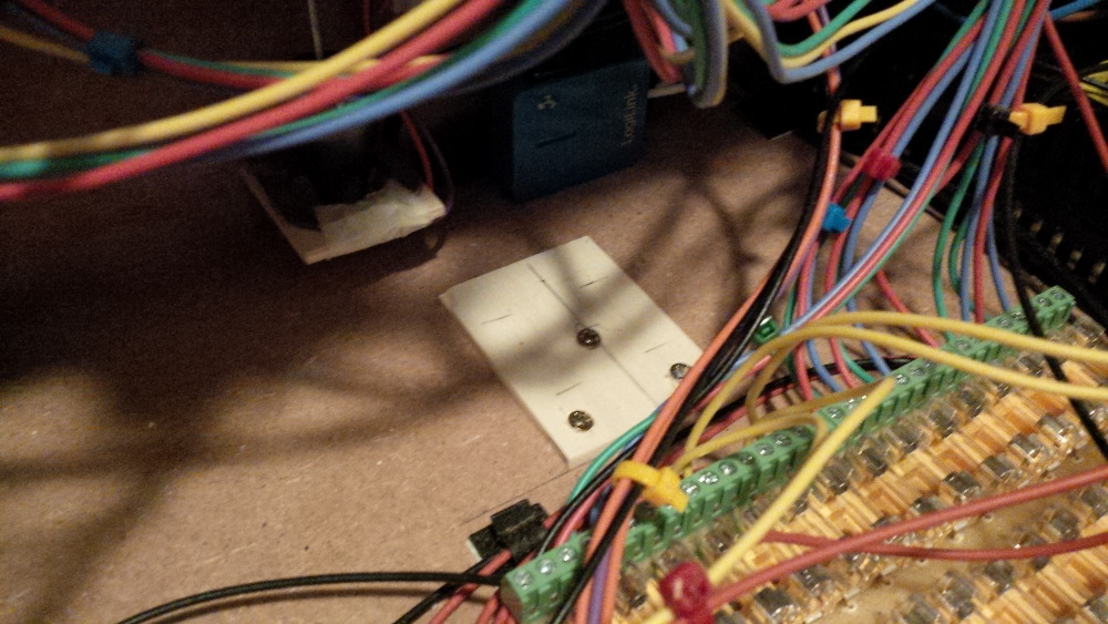
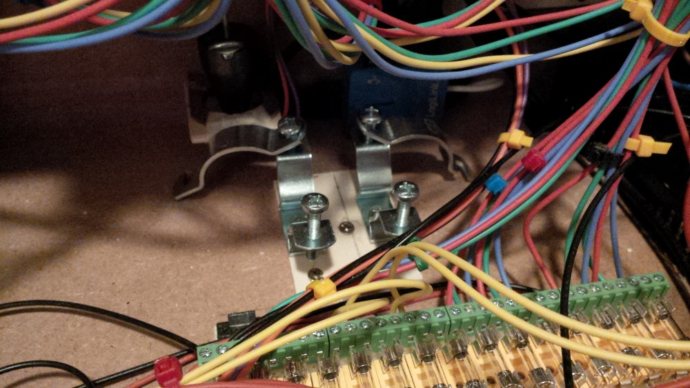
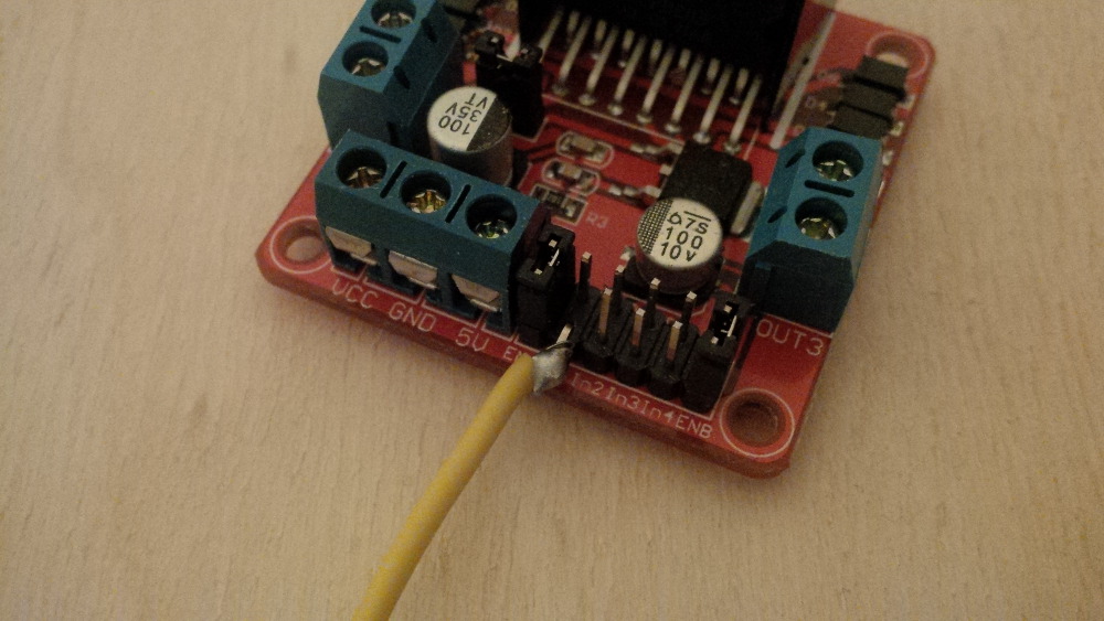
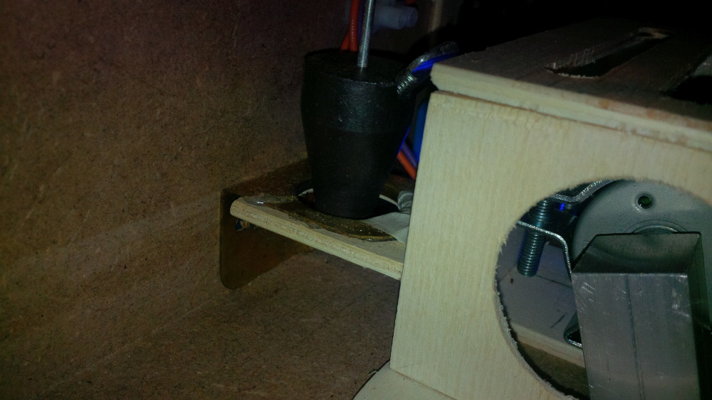
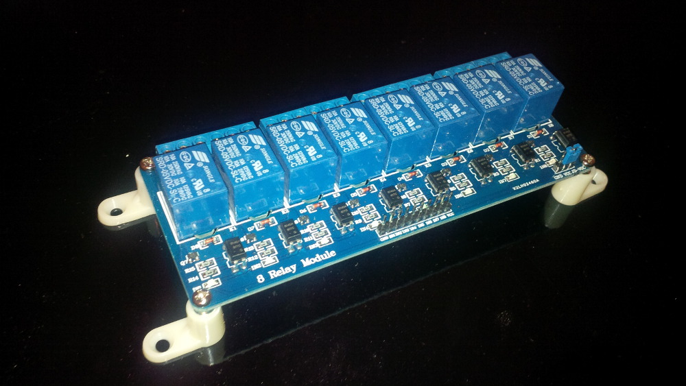
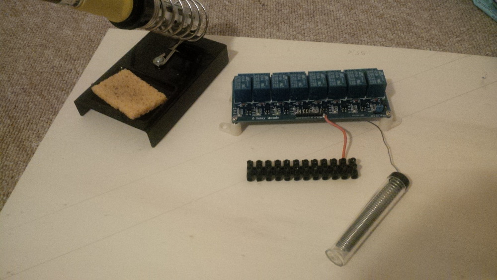
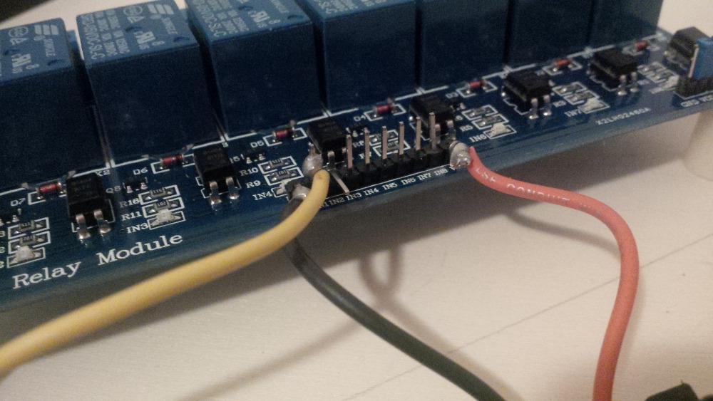
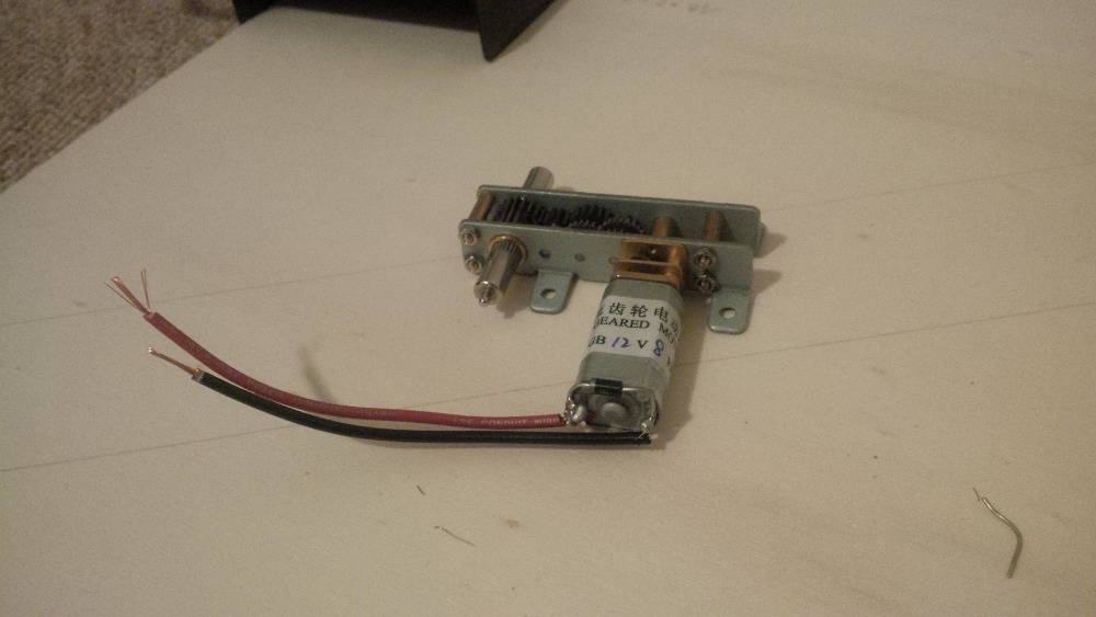
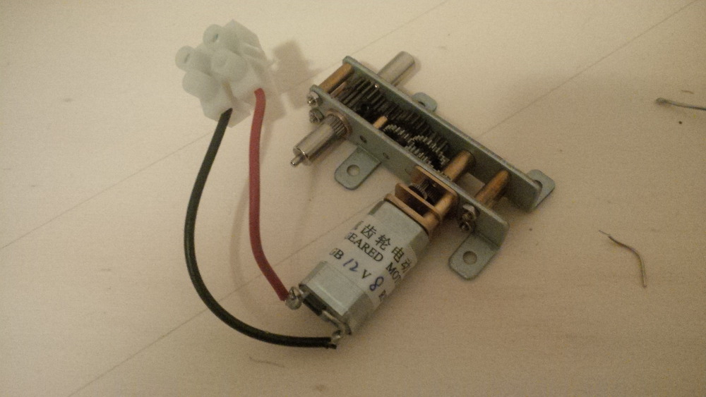
After being amazed by all the small gear wheels of this component I soldered wires to both motor pins and adjusted a terminal block. In this case we don't need to setup a bridge as motor driver. The gear motor will just run or stop.
 
chapter-27-02-gear-motor-soldering.jpg
 
chapter-27-03-gear-motor-soldering.jpg
 
From my point of view the right place for the motor is on the top plate close to thenar of players hand. Maybe it will be possible to feel a soft vibration when the gear motor is running to get a bonus effect. 
 
chapter-27-04-gear-motor-mounted.jpg
 
Because the relay board was already setup as preparation it wasn't a big deal to wire the gear motor. Then I directly wanted to run a test and was excited like a child to see the gear motor in action.
 
I didn't expect any issues, because the relay board already worked well.
 
But - holy shit! It wasn't working. WTF. Okay - to setup this component should be so simple that I will probably find the failure easily, so let's start debugging...
 
...hmmm... after a while I noticed that all wires looks fine. What is wrong?!
 
The gear motor is not working when I switch the relay to on while an LED is indicating that the relay works well.
And the motor is not damaged, because it runs when being directly connected to the 12V line.  
 
"It's a kind of magic - maaaagic..."
 

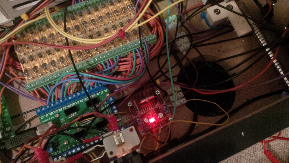
Probably I made an mistake on the relay output circuit and I started measuring the ports in different relay states. I wrote a call for help in this great forum: Unexpected relay board behavior


...
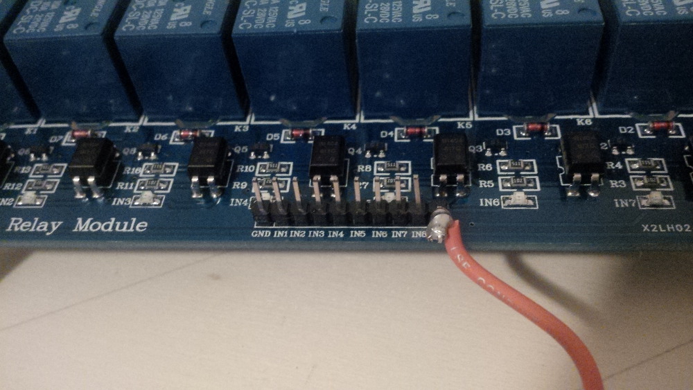
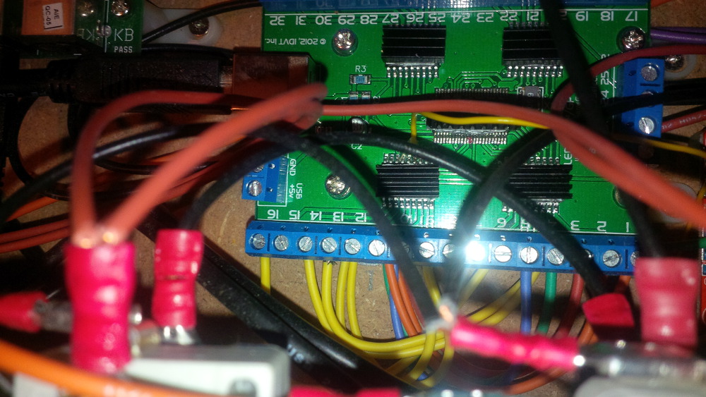
Every relay has three connectors that I interpret as IN, NC and NO.
  • IN is connected to my 12V GND.
  • NC is not connected.
  • NO is connected to DC- of my 12V toy.
...


Just a few hours later kiwi explained shortly that I interpreted the relay ports wrong. 

...
The first terminal is NC,
the second COM, or as you call it IN,
and the third is NO.
...


Thx to kiwi again!
 
After switching the ports it worked well and I was able to enjoy real gear effects.
Sooo cool.  :aikido: 
 
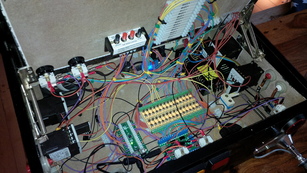
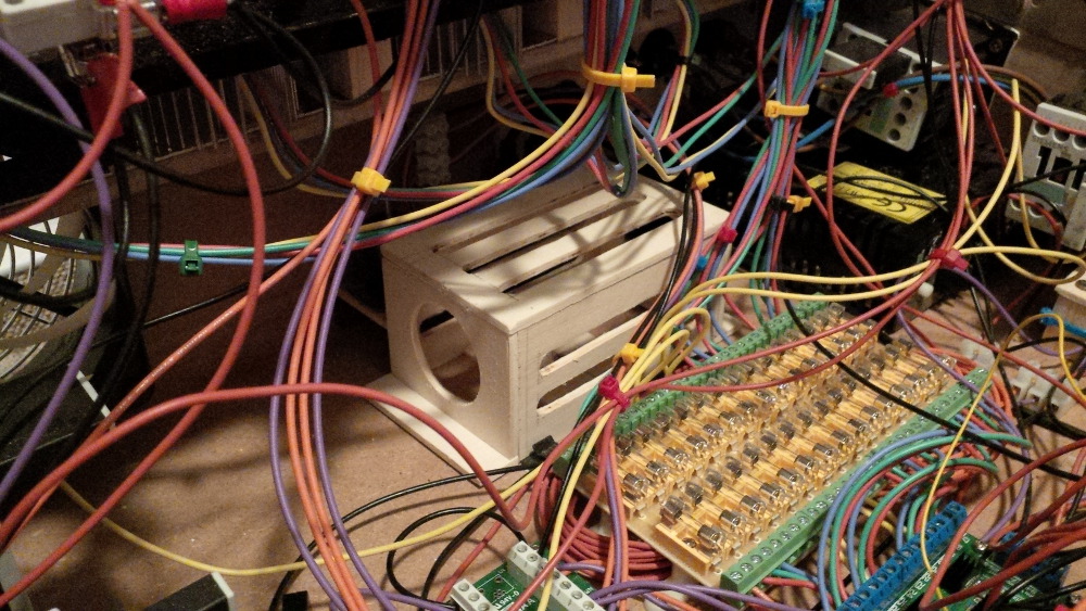
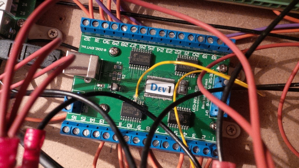
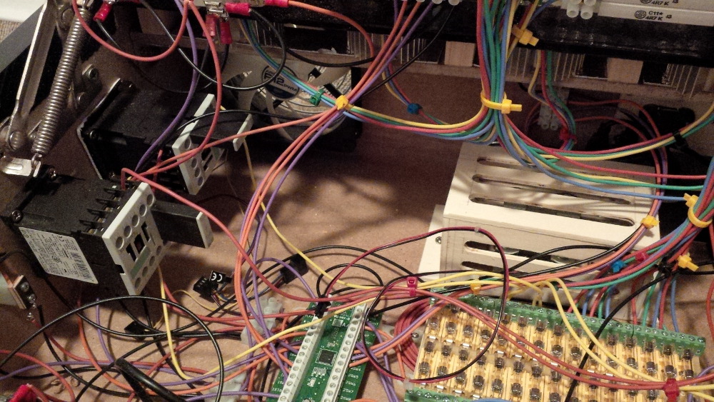
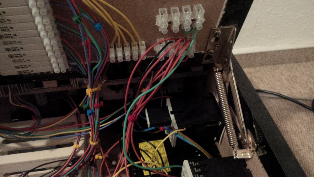
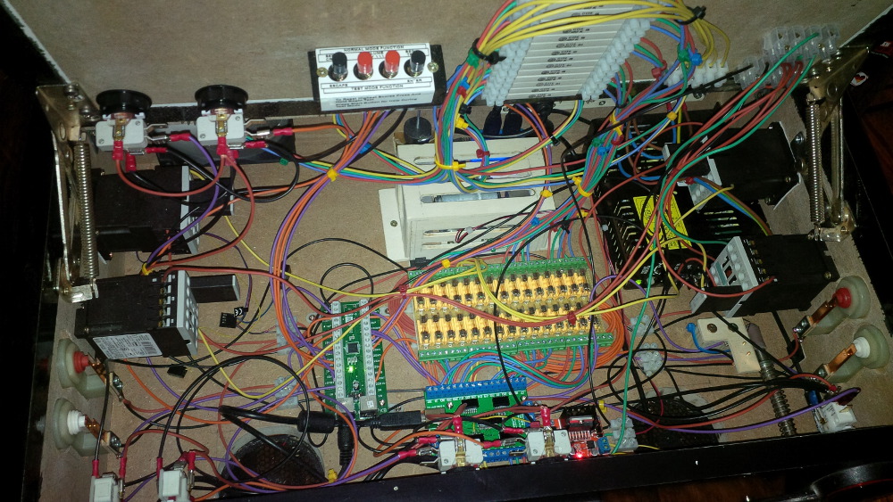
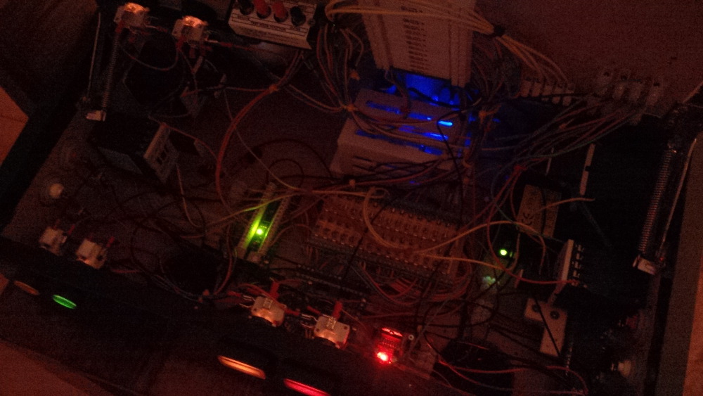
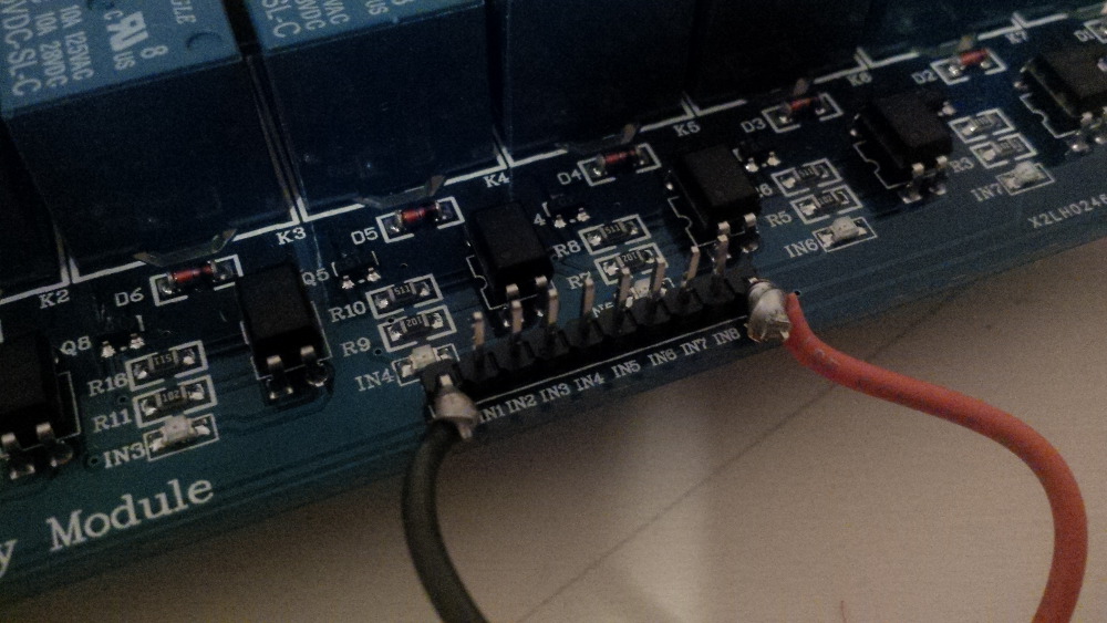
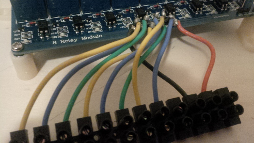
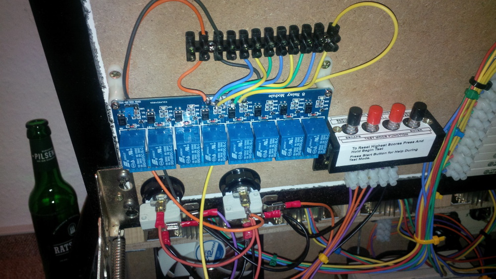
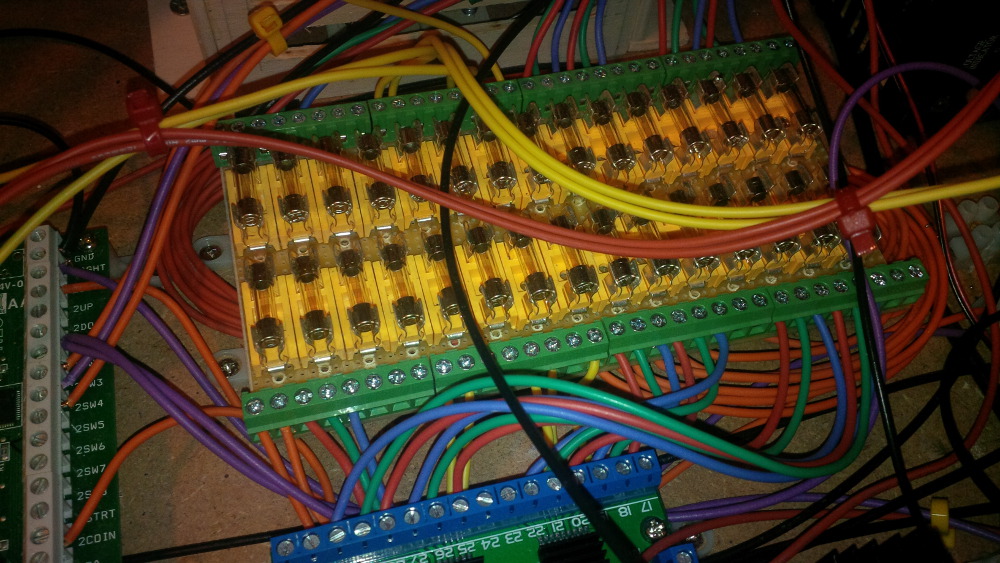
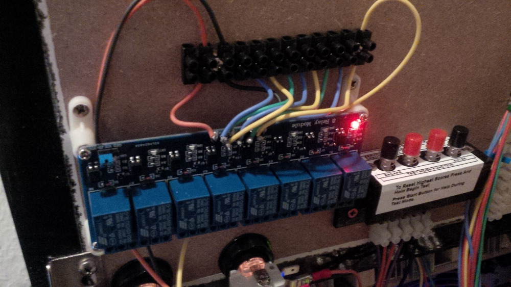
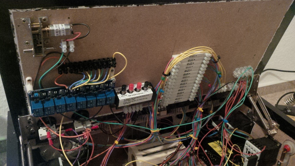
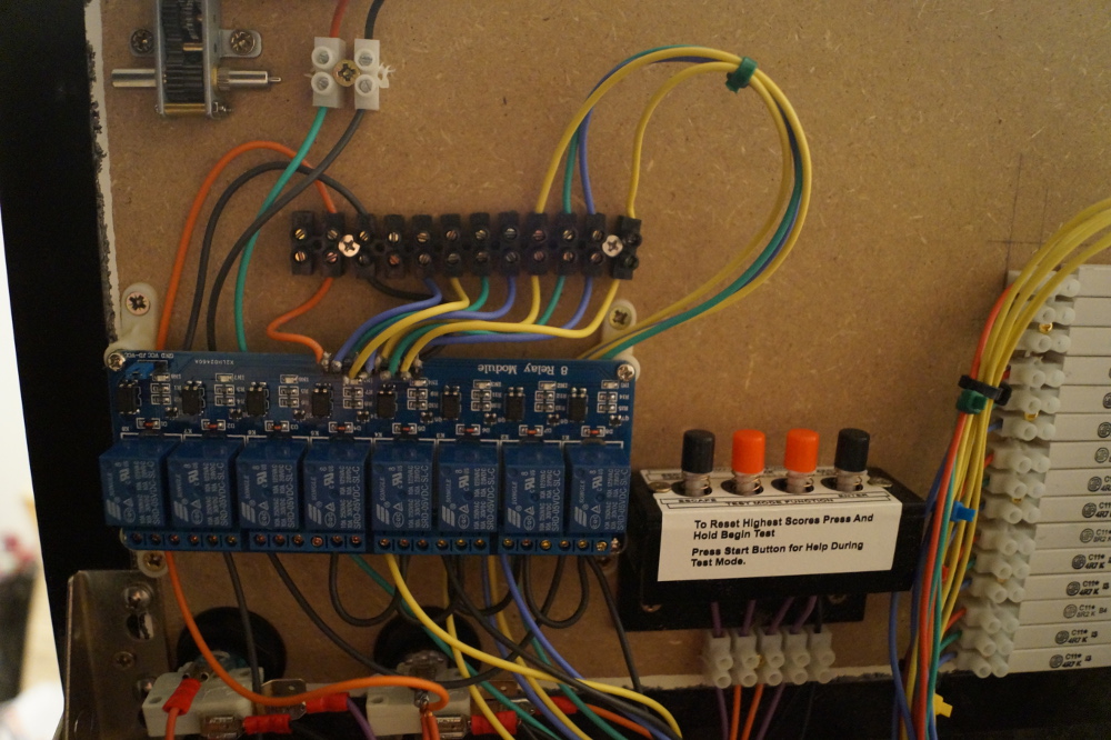
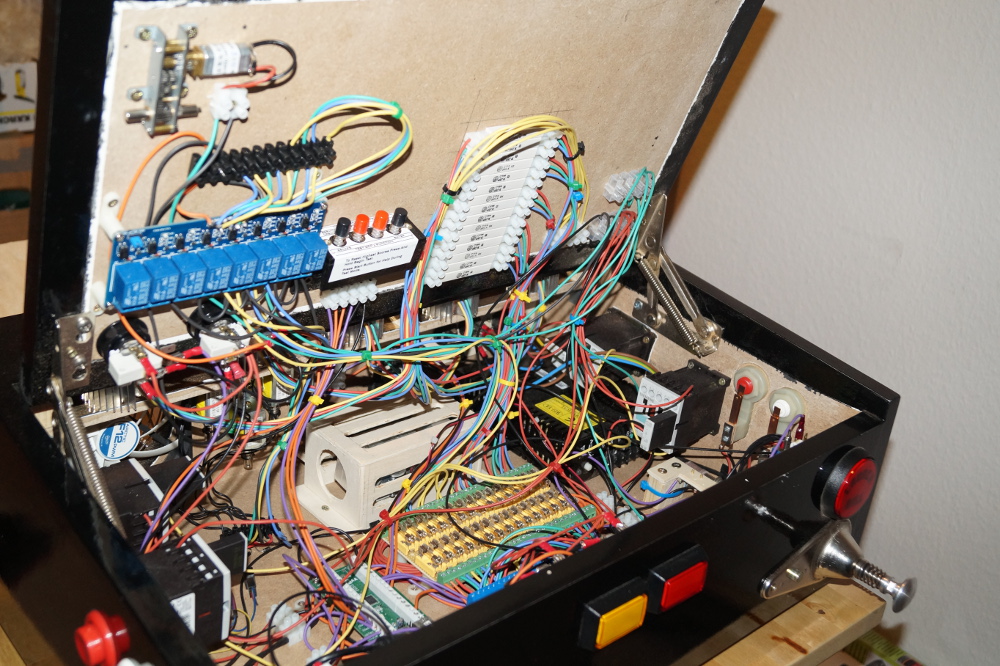
Here take a look to the current relay board wiring.
 
chapter-27-05-surprisingly-new-wires.jpg
 
But what is this?
...
Is something confusing you?
...
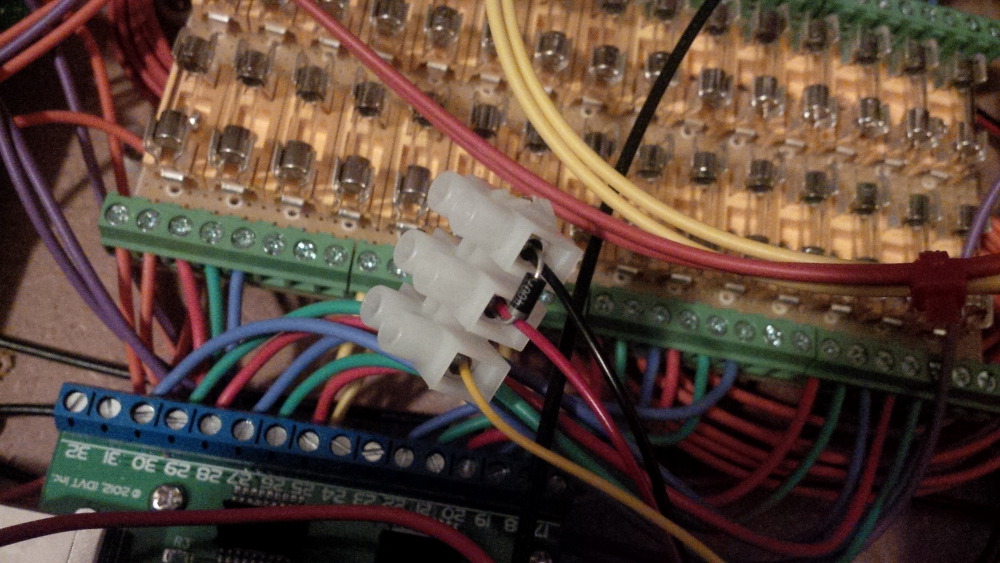
Yes. There are three more toys connected to the relays yet.
...
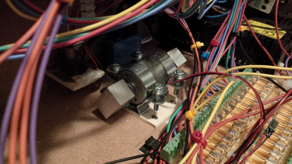
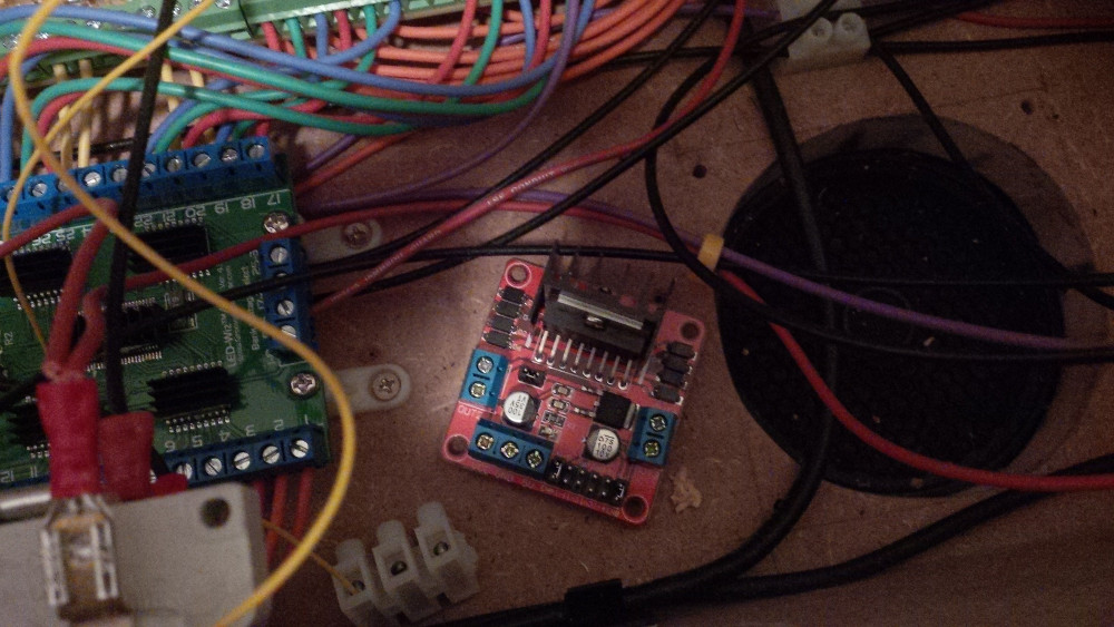
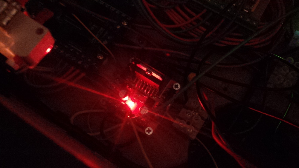
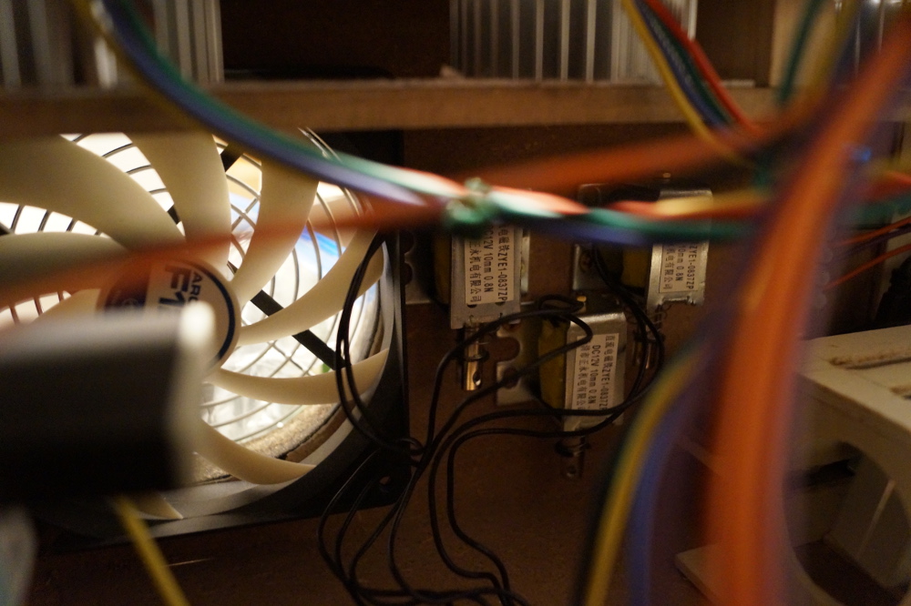
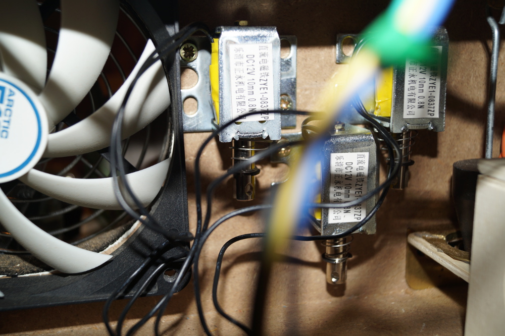
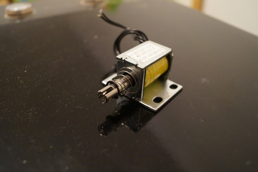
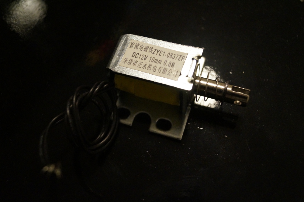
Let's follow the wires. Ohhhh, there are three new made in China solenoids mounted and already wired.
 
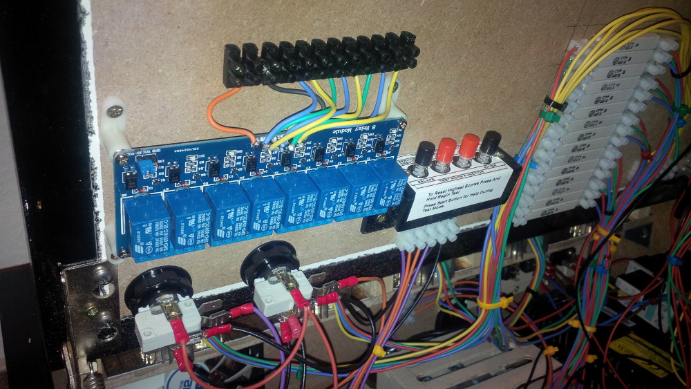
Surprise, surprise! This is the current bumper setup as an experiment.   :B): 
 
chapter-27-06-bumper-solenoids.jpg
 
chapter-27-07-bumper-solenoids.jpg
 
I chose these solenoids and ordered them for just a few Euros from China. It took a while but they arrived and are working fine.
 
chapter-27-08-china-solenoids.jpg
 
chapter-27-09-china-solenoids.jpg
 
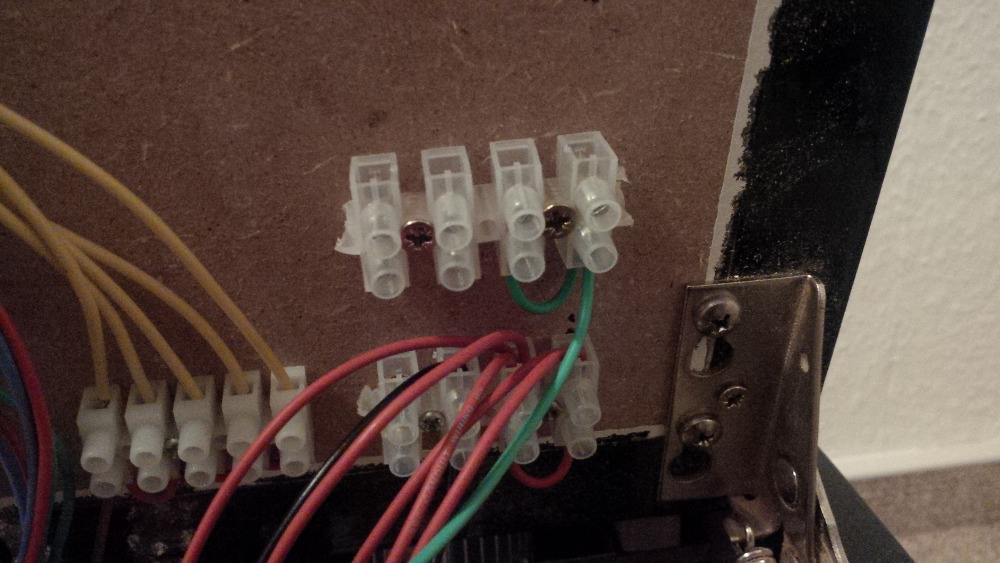
The setup is not perfect for a bumper effect. The solennoids produce a loud and strong metallic noise - "pak pak pak". For the bumpers I would like to have a more smooth plastic like sound - "pok pok pok". Maybe it's possible to mount some plastic on top of the solenoids to develop the right effect (I saw something like this in another build thread). Unfortunately it's very uncomfortable to work on this location in my box and I made no progress with this issue until yet.  
 
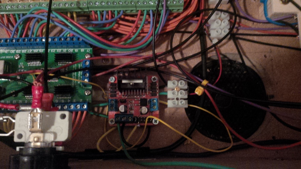
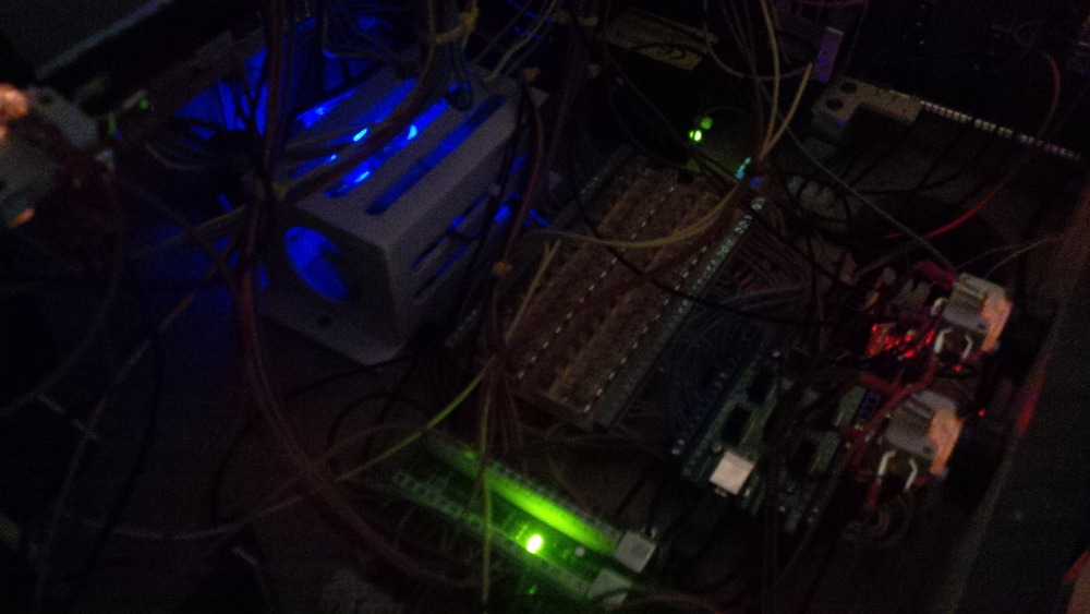
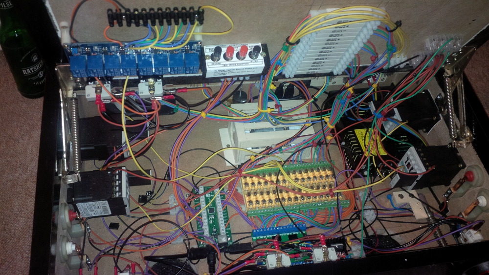
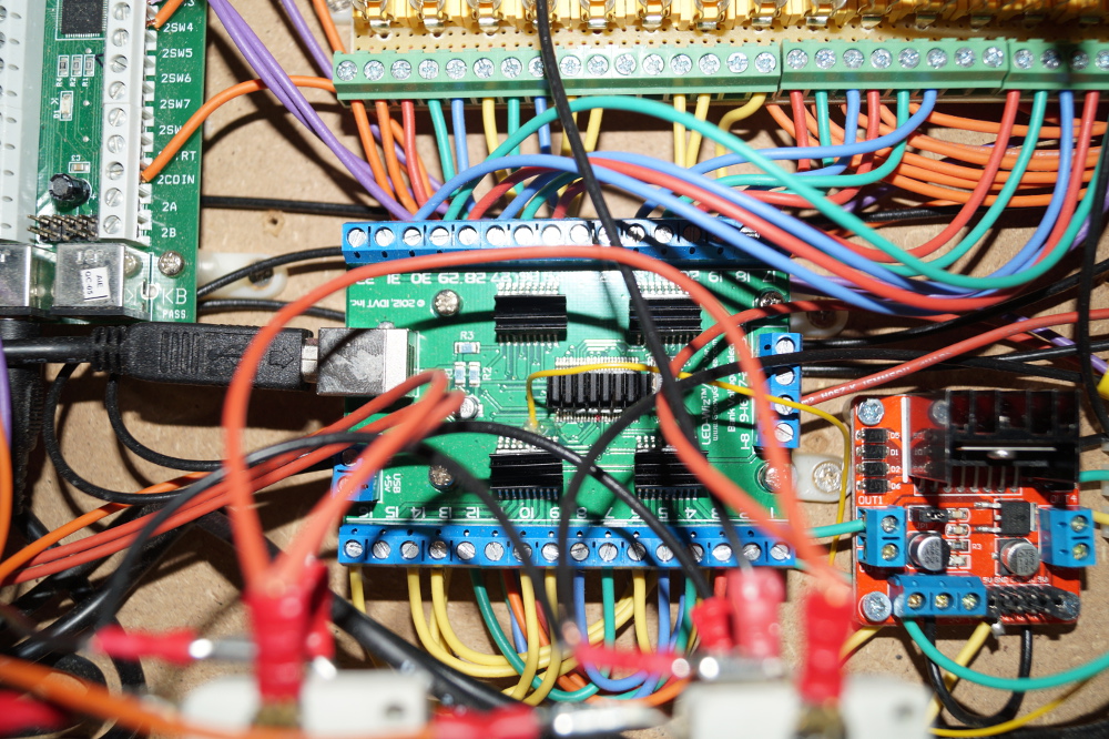
Here's the current LEDwiz status. A lot of ports are reserved but some are still unused, so that I can work on connecting some more stuff.
A cool thing could be a replay knocker for example: I still have a China solenoid left and an original knock plate - that should work, shouldn't it?
 
chapter-27-10-ledwiz-status.jpg
 
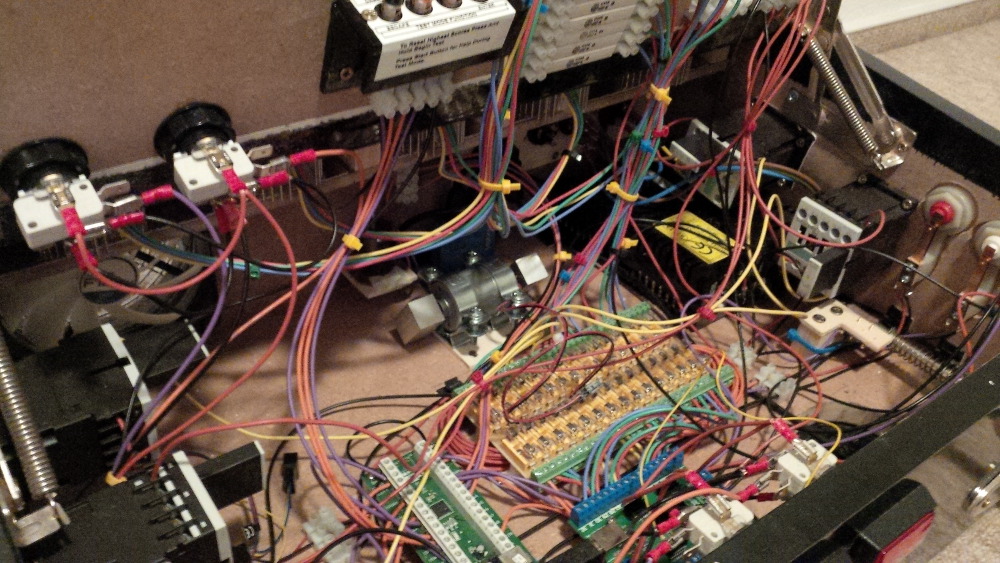
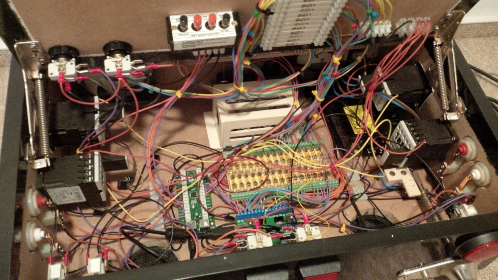
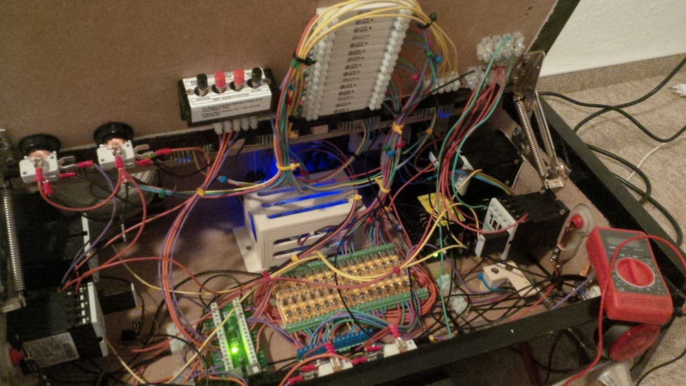
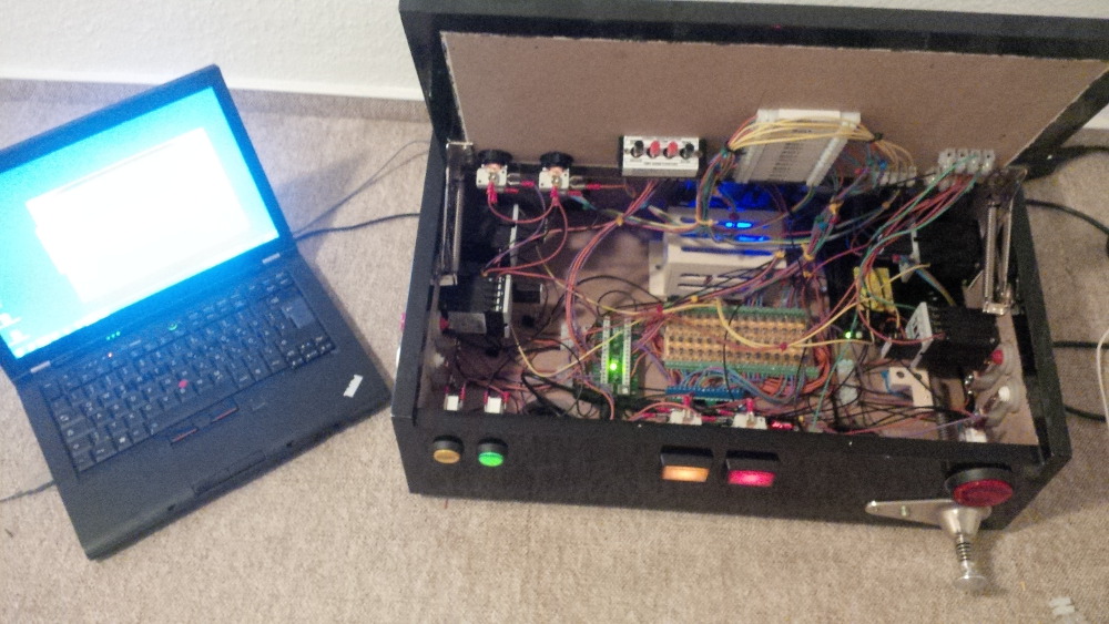
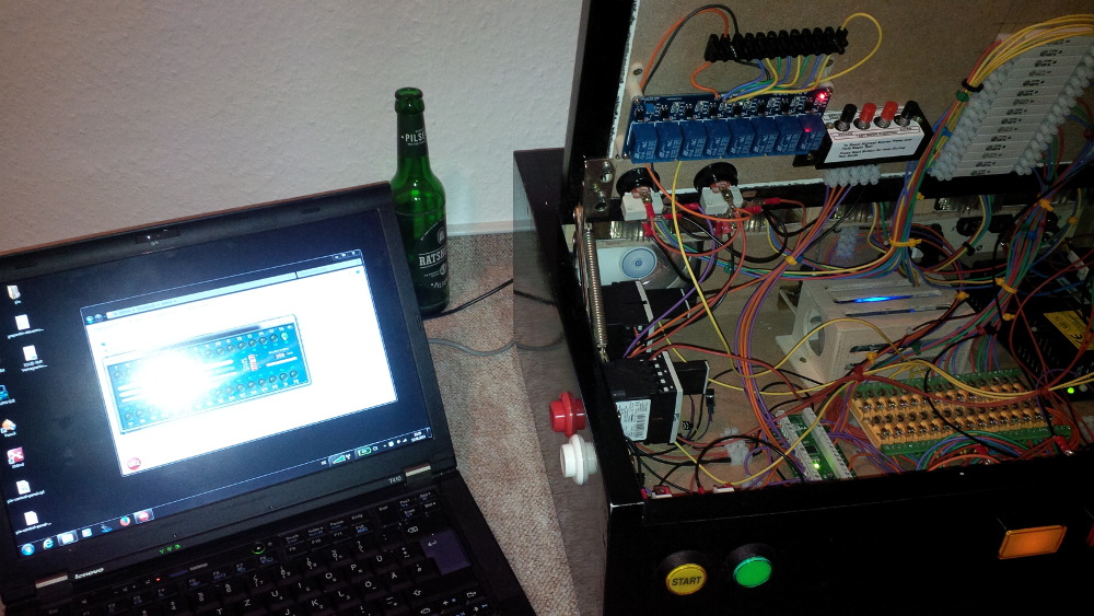
And last but not least the current system overview.
 
chapter-27-11-overview.jpg
 
Soooo, now I got my build thread in sync with reality. That feels good... like solving a debt.
 
Let's see what is coming next!

Edited by rasm, 11 September 2022 - 08:56 AM.

Visit my build: Yet another build thread


Also tagged with one or more of these keywords: Pinball Wizard, DIY, Pinball Controls, Small, Box