

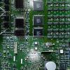


Because some people - including myself - have builtup a virtual pinball machine with these great and inexpensive DIY-boards from mjr, or perhaps intend to do so, the need arose to be able to test the various Pinscape-ICs in a really simple way. Sure, one can also test the ICs, as far as they are socketed, by swapping them for test of functionality. But that's quite cumbersome when the boards are installed in the Cabinet and you're up to your belly button in the pinball cab and at first have to disconnect half of the bunch.
For that reason I have designed a testboard and programmed some software for testing the main parts of the pinscape-PCBs. The software lights up LEDs connected to the outputs of the devices to see if its working
There are two ways to setup the test board:
- on a breadboard (size with 830pins) with jumper wires as connection
- on a single side prototype PCB-breadboard with wire connections on the top side and solder wiring on the bottom side
- (ultimately as a "real" PCB, but that won't be worth it for cost reasons)
Not much is needed as components. Details in the BOM list attached.
An USB cable with Micro-USB is sufficient as power supply, requires max. 80mA.
The board can be used to test:
- TLC5940
- ULN2064
- PC847 / PC817
- ICM7555
- power mosfet
To buil it up on the prototype PCB-breadboard is more time-consuming than on a simple breadboard, but it is stable and reusable.
It has proven as useful to print out the PCB file from KiCAD 1:1 and glue it to the prototype board. This makes it easier to see which connection goes where.
The red connections are the jumpers on the top side, the blue ones are the solder connections on the bottom.
The routing is done in 2.54mm pitch so that it fits both for the prototype pcb-breadboard and for the breadboard.
The selection which component is to be tested is set by one jumper at the top left.
The software was written in C# and can be used with the Arduino IDE or Microsoft Visual Studio.
The TLC5940 library is needed, install it in the Arduino IDE.

For Visual Studio, it is the easiest way to copy the lib directory to the "lib" subdirectory of the project directory.
Then rename the source code file "Test-Pinscape-ICs.ino" to "main.cpp" for use in VS.
Some pics of the board

first stage of populating the components, PCB ist printet out from KiCAD in 1:1 and glued to the top side of the prototype pcb

completed top side

bottom side

Test of TLC5940

Test of ULN2064

Test of PC847

Test of PC817

Test of a MOSFET
The cost for the parts is around €24-30 including €6 shipping costs for components.
All files (the KiCAD files, the BOM and the source-code) are available at this link:
https://mega.nz/fold...0J3WvgdgxRq4VqQ
(can't upload such files here)
For an easier understandig of the pinsape pcb and troubleshooting, I had made a simplifed schematic of their stages with measurement values in this thread:
https://www.vpforums...561#entry502931
There is also a link to my smd2dip-adapter, which I have used here for testing
 Top
Top


 are all trademarks of VPFORUMS.