Jump to content


Photo
* * * * * 1 votes

DIY Analog Plunger


  • Please log in to reply
1 reply to this topic

#1 igortor4

igortor4

    Neophyte

  • Members
  • Pip
  • 4 posts

  • Flag: Brazil

  • Favorite Pinball: BTTF

Posted 04 August 2020 - 03:38 PM

After several days searching for a good DIY analog plunger I coudn't find anything that fits in my pocket. So I started a project with a Arduino Uno(actually a chinese version), but it works just fine. First of all: if you have a regular version of Arduino good for you , because you can just install UnoJoy and use your plunger. But if you bought a copy of arduino (like the CH340) you can follow this tutorial:


First of all, if you dont have any Arduino background I recommend you to search some videos about Arduino. Then follow this steps:


After downloading everything plug your potenciometer in your arduino like this:

potentiometer_GOfjc4usXe.png

You can use any analog port.


Then upload the following code to your arduino (this code is available in the vJoy directory):


#include "ibus.h"
 
 
// //////////////////
// Edit here to customize
 
// How often to send data?
#define UPDATE_INTERVAL 3 // milliseconds
 
 
// 1. Analog channels. Data can be read with the Arduino's 10-bit ADC.
// This gives values from 0 to 1023.
// Specify below the analog pin numbers (as for analogRead) you would like to use.
// Every analog input is sent as a single channel.
#define NUM_ANALOG_INPUTS 1
byte analogPins[] = {0}; // element count MUST be == NUM_ANALOG_INPUTS
 
 
// 2. Digital channels. Data can be read from Arduino's digital pins.
// They could be either LOW or HIGH.
// Specify below the digital pin numbers (as for digitalRead) you would like to use.
// Every pin is sent as a single channel. LOW is encoded as 0, HIGH - as 1023
#define NUM_DIGITAL_INPUTS 0
byte digitalPins[] = {}; // element count MUST be == NUM_DIGITAL_INPUTS
 
 
// 3. Digital bit-mapped channels. Sending a single binary state as a 16-bit
// channel is pretty wasteful. Instead, we can encode one digital input
// in each of the 16 channel bits.
// Specify below the digital pins (as for digitalRead) you would like to send as
// bitmapped channel data. Data will be automatically organized in channels.
// The first 16 pins will go in one channel (the first pin goes into the LSB of the channel).
// The next 16 pins go in another channel and so on
// LOW pins are encoded as 0 bit, HIGH - as 1.
#define NUM_DIGITAL_BITMAPPED_INPUTS 0
byte digitalBitmappedPins[] = {}; // element count MUST be == NUM_DIGITAL_BITMAPPED_INPUTS
 
 
// Define the appropriate analog reference source. See
#define ANALOG_REFERENCE DEFAULT
 
// Define the baud rate
#define BAUD_RATE 115200
 
// /////////////////


#define NUM_CHANNELS ( (NUM_ANALOG_INPUTS) + (NUM_DIGITAL_INPUTS) + (15 + (NUM_DIGITAL_BITMAPPED_INPUTS))/16 )
 
 
IBus ibus(NUM_CHANNELS);
 
void setup()
{
  analogReference(ANALOG_REFERENCE); // use the defined ADC reference voltage source
  Serial.begin(BAUD_RATE);           // setup serial
}
 
void loop()
{
  int i, bm_ch = 0;
  unsigned long time = millis();
 
  ibus.begin();
 
  // read analog pins - one per channel
  for(i=0; i < NUM_ANALOG_INPUTS; i++)
    ibus.write(analogRead(analogPins[i]));
 
  // read digital pins - one per channel
  for(i=0; i < NUM_DIGITAL_INPUTS; i++)
    ibus.write(digitalRead(digitalPins[i]) == HIGH ? 1023 : 0);
 
  // read digital bit-mapped pins - 16 pins go in one channel
  for(i=0; i < NUM_DIGITAL_BITMAPPED_INPUTS; i++) {
    int bit = i%16;
    if(digitalRead(digitalBitmappedPins[i]) == HIGH)
      bm_ch |= 1 << bit;
 
    if(bit == 15 || i == NUM_DIGITAL_BITMAPPED_INPUTS-1) {
      // data for one channel ready
      ibus.write(bm_ch);
      bm_ch = 0;
    }
  }
 
  ibus.end();
 
  time = millis() - time; // time elapsed in reading the inputs
  if(time < UPDATE_INTERVAL)
    // sleep till it is time for the next update
    delay(UPDATE_INTERVAL  - time);
}
 
Note that the bold part of the code is where you define where you plugged your potenciometer. Upload this code to your arduino.
Now you have to overwrite some dlls at vJoySerialFeeder directory, just go to >> c:\Program Files\vJoy\x86 and copy two dlls: vjoyinterface.dll and vjoyinterfaceWrap.dll.
Put these dlls at vjoyserialfeeder directory. Then open vJoySerialFeeder and connect to your serial communication port (COM1, COM2...). Now, click on Add Axis and configure your potenciometer scale.
 
Now you can set your DIY plunger in Visual Pinball, but if your computer is in another language, rather than english, you may have problems with future pinball, to solve this problem just download a winXP dll an put into the Future Pinball's directory. You can download this dll here: http://download1321....9ig/dinput8.dll
 
EDIT: I didn't explained how everything works, but if you have any questions just leave a comment!

Edited by igortor4, 04 August 2020 - 05:34 PM.


#2 ralphberner

ralphberner

    Neophyte

  • Members
  • Pip
  • 8 posts

  • Flag: Switzerland

  • Favorite Pinball: who dunnit

Posted 11 January 2025 - 02:34 PM

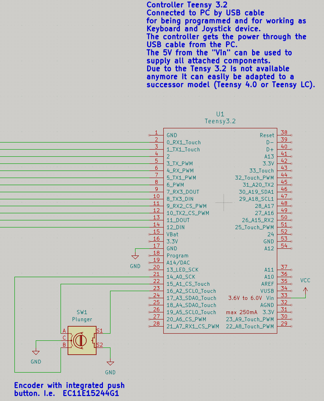
Inspired by this post i did a plunger with an Teensy controller.
I use a encoder with integrated push button. But you can keep the encoder and the push button separate of course.
It is maybe easily implemenmtable with cheaper ESP controllers too, but the libraries for keyboard an joystick emulation are well integrated for Teensy controllers. There is no need for any virtual joystick drivers. the Teensy does it all.

There are keyboard an joystick libraries available for cheap ESP32 controllers. Give it a try if you like.


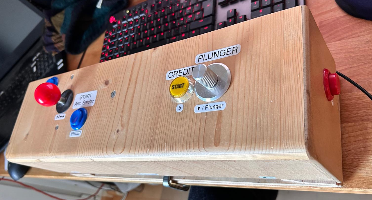
It is an enhancerment of a Pinball console i made long ago:

Konsole.png
This is the description of the console as it was that time for those who need more inspiration.
https://www.instruct...l-Console-for-/

Schematic
SNAG-0085.png

The code for the Plunger and the push button:

/*
For Teensy 3.2
IMPORTANT: For compilation set the fololwing parameteres in the Arduino IDE Tools Menu after having selected the Tensy board:
Board: Your teensy board connected to your PC or Laptop.
USB Type: "Keyboard + Mouse + Joystick" (Keybard is needed for the push button / Joystick is needed for the encoder output)
Keyboard Layout: "German Swiss" / (needs to be schecked for other countries)
CPU speed: 24MHz clock is sufficient by far.
*/

#include <Bounce.h> // Bounce2 by Thomas O Fredericks
#include <Encoder.h> // Encoder by Paul Stoffregen

#define LED 13  // Pin LED
#define ROT1 15  // Pin Rotary Encoder Input 1
#define ROT2 14  // Pin Rotary Encoder Input 2
#define PLU 16  // Pin Plunger Trigger

// Constant declarations
const int ReleaseDelay            =  20; // needed so FX3 Pinball can detect key triggers
const int ButtonDebounce          =   5; // Debounce time for light barriers
const int NUDebounce              = 300; // Prevention of double triggers for both light barriers
const int MaxPosition             = 300;  // Maximum button rotation: 80 equals 360° (Encoder makes 20 notches per rotation and 4 steps per notch)
const int StartPosition           = 270;  // Plunger jumps to this position at start of rotation. So one doesn't need to start from zero each time. Must be smaller than MaxPosition
const int MaxPositionOut          = 1000;  // Maximum position as output value
const unsigned long PlungerZyklus = 50; // Cycle time (ms) for plunger query
const int EncoderMin              = 6; // Minimum encoder value to be considered as operatded (vibration filter)
const int PlungerTimeToMax        = 500; // Time for maximum plunger pull

//Buttons declaration:
Bounce buttonPLU  = Bounce(PLU, ButtonDebounce);

// Encoder declaration
Encoder Knob(ROT1, ROT2); // ROT1 and ROT2 can be switched to change the knob dirrection if desired

// Varaiable declaration
unsigned long PreviousPlungerMillis;  // For plunger time loop
unsigned long CurrentPlungerMillis; // For plunger time loop
int Position  = 0;  //Encoder Position
bool KnobTurned = false;  // Encoder knob turned
int PositionOut; // Output Value for the Joystick in Windows
bool PlungerPressed = false; // Enkoder knob pressed

//███████████████████████████████████████████████████████████████
void setup()
{
  //Serial.begin(9600);
  //Serial.println("Encoder Test:");

  pinMode(PLU, INPUT_PULLUP); // Plunger trigger
  pinMode(LED, OUTPUT);       // Onboard LED useable for button checks
  Keyboard.begin(); // Start keyboard emulation
  PreviousPlungerMillis = CurrentPlungerMillis; // initialize plunger time loop
  CurrentPlungerMillis = millis(); // initialize plunger time loop
  Knob.write(0); // Reset encoder value
} // Setup
//███████████████████████████████████████████████████████████████
void loop()
{
// Update button states
buttonPLU.update();

// Evaluate buttons
//================================================
if (buttonPLU.fallingEdge()){PlungerPressed = true;}
if (buttonPLU.risingEdge()){PlungerPressed = false;}
Position = constrain(Knob.read(), 0, MaxPosition); // Read encoder value an constrain it between 0 and MaxPosition
CurrentPlungerMillis = millis();
if(CurrentPlungerMillis > PreviousPlungerMillis + PlungerZyklus) { // Perisodic Timer for plunger tasks
  // rotation detection for encoder knob:
  if ((Position > EncoderMin) && !KnobTurned){
    KnobTurned = true;
    Position = StartPosition; // start movement with the Startposition istead from zero
  }
  // Evaluate knob rotation:
  if (KnobTurned) // Encoder knob turned
  {
    if (PlungerPressed) // Encoder knob pushed
    {
      Knob.write(0); // reset encoder value
      Joystick.X(0); // release joystick
      KnobTurned = false;
      PlungerPressed = false;
      Position = 0;
      PositionOut = map(Position, 0, MaxPosition, 0, MaxPositionOut); // scale Position to th out value for the joystick
    }
    Knob.write(Position); // update encoder value
    PositionOut = map(Position, 0, MaxPosition, 0, MaxPositionOut); // scale Position to the out range for the joystick
    Joystick.X(PositionOut); // move joystick to the current value
  }
  else // Encoder knob not turnes
  {
    if (PlungerPressed){Keyboard.press  (KEY_UP_ARROW);}
    if (!PlungerPressed){Keyboard.release  (KEY_UP_ARROW);}
  }
PreviousPlungerMillis = CurrentPlungerMillis;
}   
// Serial.print("  Position = ");
// Serial.print(Position);
// Serial.print("  PositionOut = ");
// Serial.print(PositionOut);
// Serial.print("  KnobTurned = ");
// Serial.print(KnobTurned);
// Serial.print("  Button = ");
// Serial.print(!digitalRead(PLU));
// Serial.print("  PlungerPressed = ");
// Serial.print(PlungerPressed);
// Serial.println();
//================================================
// Onboard LED for control purposes for the keys and light barriers
digitalWrite(LED, !digitalRead(PLU)); // LED ansteuern
} // loop

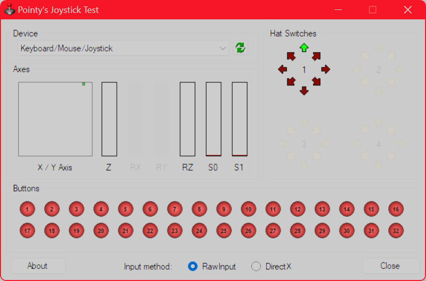
Testing the Joystick in windows:
SNAG-0087.jpg


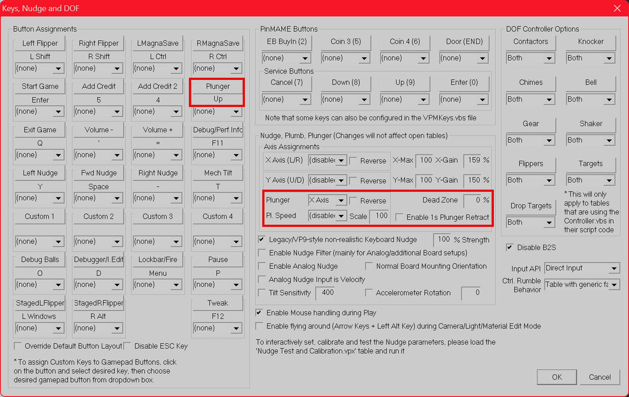
Settings in VPX:

SNAG-0086.png


What the code sample does...

For pinballs without an analog plunger, you can just press the button. In this case it simulates a hit of the up key.
For Pinballs with analog plunger you have two possibilities:
a.) You just push the button without turning it before. Then the plunger will pull back as long as you press the buton and will release together with the button. That's the same behavior as with the keyboard.
b.) You turn the knob first. After turning a little the position jumps to abot 80% from where you can adjust the desired position. after pressing the button the plunger will be released from that position.
You can adjust the behavior by the constant parameters in the code. I found the settings in the example quite suitable.

Hints...
If the controller works as a joystick, the windows control panel didn't show up the analog position at all. There are free tools available wich show everything propperly.

I.E. "VPC Joystick Tester" that is part of the VPS Software.
https://support.virp...ons/47000010107

Or here even online:
https://hardwaretester.com/gamepad
 

It worked for me in VPX if there is only one joystick attached to windows. If there were two or more joysticks, nothing worked. I gues it is because i found no way to choose the joystick within VPX.


Edited by ralphberner, 13 January 2025 - 01:27 PM.