Jump to content


Photo
- - - - -

Pinball Electrical 101....an addendum

wiring electrical ledwiz

  • Please log in to reply
14 replies to this topic

#1 zebulon

zebulon

    Cantankerous old B****D

  • Platinum Supporter
  • 1,172 posts
  • Location:Whitby, Ontario, Canada

  • Flag: Canada

  • Favorite Pinball: xenon, Medieval Madness, Royal Flush, Silverball Mania

Posted 12 December 2013 - 04:29 PM

Recently, while reading the threads and troubleshooting issue with members, I’ve noticed a growing trend in faults coming back to the same issue. I’m hoping that this post will help to clear up some of the mystery.
Please bear in mind that I’m trying to write this to be as clear as possible for both experienced and novice builders….. :)
 
Electromagnetic Interference (EMI) / Radio Frequency Interference (RFI)
 
 
Something to be aware of when building a cab is the RFI that everything electronic and electrical produces. When tvs are decased, in most instances some of the shielding that is designed into them is removed. As well, when you have multiple electrical appliances (tvs, amps, computer, power supplies) plugged into the same source, everything shares the noise that they generate with everything else.  Microcontrollers like what is used on the ledwiz, the virtua-pin plunger etc are very susceptible to this noise.
 
A great primer on what RFI/EMI is can be found here…http://www.on4ww.be/emi-rfi.html
 
In a nutshell, anything that operates on or conducts the movement of electrons generates interference (noise).
 
Consider an actual pinball machine. 
 
If you ever look inside an actual pinball machine, you'll see that there is a ground bus that is used to bond everything metal inside the cab and up in the head. As well, in the head where all the circuitry is, they have metal lined it to shield it from the noise produced by all the sparking from the coils firing and switches opening and closing.
 
All of that activity is going on 3-4' away from the control boards.
Now look inside your cab……..
 
Bonding vs Earthing vs Grounding
 
 
 Bonding:
 
Bonding is simply the act of joining two electrical conductors together. These may be two wires, a wire and a pipe, or these may be two Equipments.
 
Bonding has to be done by connecting of all the metal parts that are not supposed to be carrying current during normal operations to bringing them to the same electrical potential.
 
Bonding ensures that these two things which are bonded will be at the same electrical potential. That means we would not get electricity building up in one equipment or between two different equipment. No current flow can take place between two bonded bodies because they have the same potential.
 
Bonding, itself, does not protect anything. However, if one of those boxes is earthed there can be no electrical energy build-up. If the grounded box is bonded to the other box, the other box is also at zero electrical potential.
 
It protects equipment & Person by reducing current flow between pieces of equipment at different potentials.
 
The primary reason for bonding is personnel safety, so someone touching two pieces of equipment at the same time does not receive a shock by becoming the path of equalization if they happen to be at different potentials.
 
The Second reason has to do with what happens if Phase conductor may be touched an external metal part. The bonding helps to create a low impedance path back to the source. This will force a large current to flow, which in turn will cause the breaker to trip. In other words, bonding is there to allow a breaker to trip and thereby to terminate a fault.
 
Bonding to electrical earth is used extensively to ensure that all conductors (person, surface and product) are at the same electrical potential.  When all conductors are at the same potential no discharge can occur.  
 
Earthing:
 
Earthing means connecting the dead part (it means the part which does not carries current under normal condition) to the earth for example electrical equipment’s frames, enclosures, supports etc.
 
The purpose of earthing is to minimize risk of receiving an electric shock if touching metal parts when a fault is present. Generally green wire is used for this as a nomenclature.
 
Under fault conditions the non-current carrying metal parts of an electrical installation such as frames, enclosures, supports, fencing etc. may attain high potential with respect to ground so that any person or stray animal touching these or approaching these will be subjected to potential difference which may result in the flow of a current through the body of the person or the animal of such a value as may prove fatal.
 
To avoid this non-current carrying metal parts of the electrical system are connected to the general mass of earth by means of an earthing system comprising of earth conductors to conduct the fault currents safely to the ground.
 
Earthing has been accomplished through bonding of a metallic system to earth. It is normally achieved by inserting ground rods or other electrodes deep inside earth.
 
Earthing is to ensure safety or Protection of electrical equipment and Human by discharging the electrical energy to the earth.
 
Grounding:
 
Grounding means connecting the live part (it means the part which carries current under normal condition) to the earth for example neutral of power transformer.
 
Grounding is done for the protections of power system equipment and to provide an effective return path from the machine to the power source. For example grounding of neutral point of a star connected transformer.
 
Grounding refers the current carrying part of the system such as neutral (of the transformer or generator).
 
Because of lightening, line surges or unintentional contact with other high voltage lines, dangerously high voltages can develop in the electrical distribution system wires. Grounding provides a safe, alternate path around the electrical system of your house thus minimizing damage from such occurrences.
 
Generally Black wire is used for this as a nomenclature.
 
All electrical/electronic circuits (AC & DC) need a reference potential (zero volts) which is called ground in order to make possible the current flow from generator to load. Ground is May or May not be earthed. In Electrical Power distribution it is either earthed at distribution Point or at Consumer end but it is not earthed in Automobile( for instance all vehicles’ electrical circuits have ground connected to the chassis and metallic body that are insulated from earth through tires). There may exist a neutral to ground voltage due to voltage drop in the wiring, thus neutral does not necessarily have to be at ground potential.
 
In a properly balanced system, the phase currents balance each other, so that the total neutral current is also zero. For individual systems, this is not completely possible, but we strive to come close in aggregate. This balancing allows maximum efficiency of the distribution transformer’s secondary winding
 
 
What does this mean????
 
I’ll put it less confusing terms.
 
Bonding is running a bus, cable, sheet or braid of conductive material (let’s say wire) from part to part to ensure that all the parts in the chain are connected. Ever noticed that the standoffs on the back of the tv in your pincab are metal and screwed into the sheet metal of the frame of the tv? That’s bonding. The metal screw, metal standoff and metal frame are acting together to get the ground on the circuit board to the ground on the frame from where it will eventually bond to another circuit board.
 
Earthing and grounding are essentially the same. There is a minor variance, but we’ll ignore that as none of us are splitting atoms in our pincabs. Earthing for our purposes is providing a safe and effective path for the completion of the circuit so that the tv and computer turns on and we can push a button on the coindoor without becoming part of the circuit and frying ourselves like a strip of bacon.
 
OK…I’ve gotten this far…so what???
 
Many are ignoring the basics of what will make their cabs run efficiently and trouble-free.
 
Some tips……
 
Wiring
 
We’ve all seen these pics right?
 
Indian+power+lines.jpg
 
 
power-lines.jpg
 
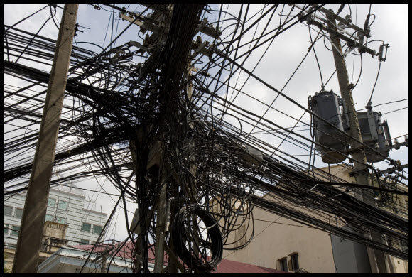
Somehow this works for them…but probably not very efficiently. Amazingly enough, they are still able to get telephone communication signals through that mess so that they can answer your call for support for your Microsoft product that you’re having trouble with… :D
 
Wiring your cab like the above pics will not work for very long and will be impossible to troubleshoot.
 
When I was young, cute and full of promise I worked as a car audio installer. We had a rule of thumb that signal lines and power lines didn’t mix. Ever had a car stereo that emitted a whine in synch with the engines RPM? That’s why. Having heavy draw power lines next to lighter amperage signal lines allows for noise (EMI/RFI) to be injected into the signal line…it doesn’t have the strength to fight it off. Now we’re not worrying so much about sound signals in a pincab…but the theory still applies.
 
I recently built myself a cnc router with a variable speed inverter from China to power the spindle. Maxxsinner thoughtfully provided me with the shielded cable to connect the inverter to the spindle so I will go out on a limb here and guess that it wasn’t cheap cable (he is after all a cabbie in Queens, NYC who likes to affect an Australian accent and pretend to be an electrician… :D
 
The machine is bonded, the cable is bonded and still to this day, if I move one of the proximity switch wires in the cable carrier by even 2mm or more, the limit switch will trigger when the spindle turns on and throw the machine into reset.
 
The point I’m trying to make is to keep your wiring as tidy and logical as possible and that when things go wrong…try changing the placement of the component or wiring for the component. You may find that it’s just a matter of mm’s to get away from the noise that is giving you trouble.
 
Bonding
 
Back to that again????
 
Yup.
 
Bond the metal frame of your coindoor, the legs of your pincab, the frames of your noisy, decased tv’s, the can on the shaker motor, the case of your power supply, the metal casing of your pc……if it’s metal, connect it.
 
OK..one proviso here…don’t bond the metal of heatsinks…a lot of the time the heatsink is directly connected to the transistor and therefore live (has voltage on it)….you’ll blow the hell out of it.
 
When you bond large components or span large distances…don’t use 24awg wire and expect it to be effective. Use a decent braided copper braid available at most electrical stores and automotive electrical suppliers. Ensure that there is a good, clean metal to metal connection (scrape some paint if you have to) and use a star washer where possible.
 
Placement
 
Consider the possible effect of where you locate your components. Think of every wire as a potential route for noise to get into a circuit and place your components and wire looms accordingly. 
 
That contactor for the slingshot right above the ledwiz is an electromagnet strong enough to hold 6 or 8 heavy spring-loaded contacts together when it is energized. That magnetic field is going to play hell with the microcontroller on the ledwiz underneath it.
 
That shaker motor is an electromagnet when energized, the same scenario applies there.
 
That television without any shielding is broadcasting a huge amount of EMI/RFI. The inverters that fire the cathode tubes that are used for backlighting are a huge source of noise for the circuitry inside the tv, let alone what we are putting around it in our cabs.
 
Is the plunger too close to it? 
 
Should I really cable tie the power wires for my booster board to the underside of it? 
 
Shielding
 
If you have the option, keep any shielding (the metal flashing behind the tv, covering the pcb, or whatever) intact when removing bezels, cases, etc. This stuff was designed to be there for a reason, and that reason may be why you are having troubles with your ledwiz or plunger keeps cutting out.
 
Even better, if you have the ability, make some shielding for circuits that don’t have any (booster boards, dual H bridge drivers, etc). Light gauge, ferrous metal is all that’s needed. Place it around the component in question (without shorting it out) and add it to your bonding chain.
 
Metal project boxes from electronics supply houses and surplus shops, cough drop tins, coffee cans….all are great solutions to encasing and shielding circuitry from EMI/RFI if properly bonded.
 
Summary
 
Nothing is harder or more frustrating for you than to try and troubleshoot an issue that is/may be related to EMI/RFI. 
 
You’ve spent thousands on the best parts, read years worth of development and build experiences, spoken to many experienced and novice builders alike…..and still it doesn’t work. 
 
You’re looking for an issue that you can’t see without specialized equipment in a sea of components that have been modified or built to just work. 
 
The best defense in this case is a good offense and if you plan out your build with a few of these considerations in mind you could potentially be saving yourself hours of frustration.
 
I hope this helps some of you out there.

 ZB%20%20Storefront1%20.png               [email protected]

Don't pm or expect an answer from me here ... the links above are my contacts.

I know so much about so little that I could teach you all there is to know about nothing......


#2 tonyg

tonyg

    Hobbyist

  • Members
  • PipPip
  • 21 posts

  • Flag: United States of America

  • Favorite Pinball: Spider Man

Posted 12 December 2013 - 09:55 PM

Great read for experienced, as well as novice builders such as myself. Sometimes you make good decisions without even realizing it at the time. I did not decase my playfield or backglass tv's, and all/most metal parts in my cab are bonded with copper braid. Thanks for the info ZEB!

#3 zebulon

zebulon

    Cantankerous old B****D

  • Platinum Supporter
  • 1,172 posts
  • Location:Whitby, Ontario, Canada

  • Flag: Canada

  • Favorite Pinball: xenon, Medieval Madness, Royal Flush, Silverball Mania

Posted 13 December 2013 - 12:16 AM

Glad to hear that it helps..:)


 ZB%20%20Storefront1%20.png               [email protected]

Don't pm or expect an answer from me here ... the links above are my contacts.

I know so much about so little that I could teach you all there is to know about nothing......


#4 The Loafer

The Loafer

    Pinball Wizard

  • VIP
  • 3,468 posts
  • Location:Embrun, Ontario, Canada

  • Flag: ---------

  • Favorite Pinball: Superman, Firepower & Tron


Posted 13 December 2013 - 03:41 AM

What a post, thanks Zeb!

#5 Les73gTx

Les73gTx

    Preschooler

  • Members
  • PipPipPipPip
  • 523 posts
  • Location:Maine

  • Flag: United States of America

  • Favorite Pinball: Power Play, BoP, JackBot, MM, AFM, CV, MB,Champions Pub, CftBL, ToM, and Many More

  • PS3 Gamer Tag: LCT0819, Les73gtx
  • 360 Gamer Tag: PissPoorShot

Posted 14 December 2013 - 11:08 PM

Great info for sure! :dblthumb: Myself being a old Car Audio installer from the late 80's through the 90's, I was witness to the downfall of car audio in the respects of quality ... "build it cheaper and faster and sell it for more money". I have had my share of chasing down engine EFI and the horrid engine whine.


 I have 2 questions for you Zebulon related to our cabs ...


 If we are using more than one power supply like I am (mine happen to be PC power supplies) should they be grounded together? Using the Molex connectors and removing the 12v and 5v wires and connecting the black grounds together or just run both grounds to the ground buss bar for the cab? I have my PC on a slide out tray, should I make sure that tray is in the ground loop? What about the PC power supply, in the loop (bonded and earthed) or not?


  Should we still keep the LedWiz on a separate ground loop? I have seen it posted in a few places that it should be kept in its own ground loop, but if the power supplies are connected then maybe it does not matter.


 Ok OK that was like 5 questions, sorry. I have started to pull my cab back apart because I have some small issues that is EFI related (sound cutting in and out and louder with the nudge button pushed and random windows disconnect sound from usb).


 I knew that I was going to need to do this anyways because I finished it in a hurry to show off the family that came in from out of town. Ok back to wiring


 Thank you


les73gtx___atomicpin-pc.png


#6 zebulon

zebulon

    Cantankerous old B****D

  • Platinum Supporter
  • 1,172 posts
  • Location:Whitby, Ontario, Canada

  • Flag: Canada

  • Favorite Pinball: xenon, Medieval Madness, Royal Flush, Silverball Mania

Posted 15 December 2013 - 05:15 PM

Hey sorry for the late reply,


If you are using 2 atx psus in your cab they will already be sharing the ground from the ac plugs. It doesn't hurt to bond the chassis' of the 2 together, but the shielding of the chassis is already more than enough (the circuits inside are already bonded to the chassis as well as grounded). It certainly wouldn't hurt to put the output grounds to a common point as that would help keep the outputs working properly throughout the cab.


Drawer slides are hard to get a good bond with due to the loose tolerances that the ball bearings provide in the connection. Having said that, it's not a bad idea to bond the bracket just to cut down on the possibility of them becoming an antenna.


The ledwiz will function most reliably by putting the outputs in the common loop with everything else. By that I mean connecting the gnd tab on the board to the common ground point of the cab. This is important if using something like the barebones booster board that I sell. Without a common grounding point between the ledwiz output and the power input on the booster, there isn't a complete circuit and strange things start to happen (because the circuit will seek a common grounding point, even through a positive connection).


I would bond the chassis of the pc to the system. Once again, your pc is operating on a frequency that equals microwave transmission frequencies, just not at the same strength. Ever seen the knockouts that you have to remove in order to install a new riser card or cdrom drive? Those are there to close the gap in the shielding that would exist otherwise. Your pc will become bonded by it's connection to the mains ground as well, but a braided connection will provide a much shorter and reliable connection than the rinky dink stranded wire connection inside your power supply cable.


Hope this clears things up for you.


 ZB%20%20Storefront1%20.png               [email protected]

Don't pm or expect an answer from me here ... the links above are my contacts.

I know so much about so little that I could teach you all there is to know about nothing......


#7 Les73gTx

Les73gTx

    Preschooler

  • Members
  • PipPipPipPip
  • 523 posts
  • Location:Maine

  • Flag: United States of America

  • Favorite Pinball: Power Play, BoP, JackBot, MM, AFM, CV, MB,Champions Pub, CftBL, ToM, and Many More

  • PS3 Gamer Tag: LCT0819, Les73gtx
  • 360 Gamer Tag: PissPoorShot

Posted 15 December 2013 - 05:55 PM

Thank you very much, that was the info specific to my build that I needed. Maybe some others will benefit also.


 I misspoke when I said LedWiz, I was really thinking about the iPac. But that is some very good points that I had not thought of regarding the LedWiz.


 So the iPac should be in it's own ground loop or with the rest of the chassis ground?


 Thanks again  :otvclap:


les73gtx___atomicpin-pc.png


#8 zebulon

zebulon

    Cantankerous old B****D

  • Platinum Supporter
  • 1,172 posts
  • Location:Whitby, Ontario, Canada

  • Flag: Canada

  • Favorite Pinball: xenon, Medieval Madness, Royal Flush, Silverball Mania

Posted 15 December 2013 - 06:09 PM

The Ipac is a different animal entirely.


There are no power connections on the ipac and the GND connections that are on the board are actually the source if the signal that  is being switched. 


It would be more appropriate to label it "common" so as not to confuse people into grounding it to their common bus.


 ZB%20%20Storefront1%20.png               [email protected]

Don't pm or expect an answer from me here ... the links above are my contacts.

I know so much about so little that I could teach you all there is to know about nothing......


#9 chas

chas

    Pinball Fan

  • Banned
  • PipPipPipPip
  • 1,791 posts

  • Flag: ---------

  • Favorite Pinball: i played Timezone, quickdraw, triple action, frontier and a few more

Posted 16 December 2013 - 02:30 AM

The Ipac is a different animal entirely.


There are no power connections on the ipac and the GND connections that are on the board are actually the source if the signal that  is being switched. 


It would be more appropriate to label it "common" so as not to confuse people into grounding it to their common bus.

static electricity and bad ground can do a lot of funny things......

most electronics have a electron field around it creating static electricity.....some electronics too close together can create a hummm....seperate and could not hurt to make a ground.

ex:  i have an outdoor mast mounted amp for TV on the pole and the amp behind the TV....i grounded the pole with a 10gauge wire to the ground with a stake to protect it from static electricity.....static electricity is harmful and can create alot of funny problems.


another example is the light panel on car radios.....front panel lights dancing to the music at higher volumes......probably a small cheap 18-22guage ground wire and a bad ground source.....for most use a 12-14gauge stranded wire and find a good ground source.

cheap or non-supressed spark plug wires willl crackle and whine with engine RPM.


Edited by chas, 16 December 2013 - 03:26 AM.


#10 zebulon

zebulon

    Cantankerous old B****D

  • Platinum Supporter
  • 1,172 posts
  • Location:Whitby, Ontario, Canada

  • Flag: Canada

  • Favorite Pinball: xenon, Medieval Madness, Royal Flush, Silverball Mania

Posted 17 December 2013 - 01:10 PM

Static electricity is a good point Chas, another good reason to bond the coindoor and the legs. For anyone that is reading, unless you have metal flipper buttons, bonding the siderails is unnecessary.


 ZB%20%20Storefront1%20.png               [email protected]

Don't pm or expect an answer from me here ... the links above are my contacts.

I know so much about so little that I could teach you all there is to know about nothing......


#11 chas

chas

    Pinball Fan

  • Banned
  • PipPipPipPip
  • 1,791 posts

  • Flag: ---------

  • Favorite Pinball: i played Timezone, quickdraw, triple action, frontier and a few more

Posted 17 December 2013 - 06:55 PM

Static electricity is a good point Chas, another good reason to bond the coindoor and the legs. For anyone that is reading, unless you have metal flipper buttons, bonding the siderails is unnecessary.

here is a possibilty.   alot of you are running a full cab with 2 and 3 monitors and a GFX card....cards use a lot of juice....

if it were my cab i would make a power cord for this....


i have plans to build a cab....i went to my local hardware store and bought 10ft of  3wire 12gauge cord, heavy duty industrial 15amp male/female ends to handle the huge power consumption.....maybe 20 amp male/female ends will be better....the wall outlet will need the 20amp plugin.....maybe alot of you are having trouble because you are using a cheap 14-16gauge cord....it cant handle the power consumption....the 14-16gauge ground wire is too small.....these cheap 14-16gauge cords and extension cords are for light duty.....not for this.


a good cord and 15amp plugs might be ok......be careful with 20amp

https://www.google.c...ta&channel=fflb


Edited by chas, 17 December 2013 - 07:05 PM.


#12 kenrunio

kenrunio

    Hobbyist

  • Members
  • PipPip
  • 30 posts

  • Flag: United Kingdom

  • Favorite Pinball: Attack from Mars

Posted 24 December 2013 - 09:09 AM

Zeb - question for you. My computer on-off switch is wired to a relay which turns on the power supply to everything else - similar to what is described in the Electrical 101 manual. However, every so often the relay got stuck - literally stuck in the on or closed position even after powering down the computer, and to fix it required a little tap or shake of the relay to get back to the off or open position. While I'm no expert, I assumed this was due to the high back EMF currents flowing around. 


I found a solution was to wire veristors between the mains live/earth, live/neutral and earth/neutral. My mains is 240v and the veristors I'm using are rated at 300v. The problem does not occur anymore as I assume that any excess voltage mainly from the EMFs and above 300v is shunted away from the relay.


Is this an okay solution or am I likely to kill myself playing pinball one day?!


#13 zebulon

zebulon

    Cantankerous old B****D

  • Platinum Supporter
  • 1,172 posts
  • Location:Whitby, Ontario, Canada

  • Flag: Canada

  • Favorite Pinball: xenon, Medieval Madness, Royal Flush, Silverball Mania

Posted 26 December 2013 - 03:03 PM

Sounds like you have it licked Ken. Usually you only need to install 1 varistor in the line (look at any old pinball machine for verification on this) but that's just a "cost saving" measure...it certainly isn't going to hurt anything by covering all of your bases as you have.


A quick note on my post......Reading back through it I see that I neglected to mention that bonding all metals should be done to that which is not "in circuit"...meaning that if you were using metal canned solenoids that have a ground connection through the can or body, bonding the can will defeat the switching option on these...you will be triggering all of the solenoids each time one goes live.


Bonding is for the "inert" parts of your cab, legs, tv chassis, coin door, etc and not for something that is part of a switching circuit....:D


 ZB%20%20Storefront1%20.png               [email protected]

Don't pm or expect an answer from me here ... the links above are my contacts.

I know so much about so little that I could teach you all there is to know about nothing......


#14 miracle

miracle

    Enthusiast

  • Members
  • PipPipPip
  • 243 posts

  • Flag: France

  • Favorite Pinball: TOTAN

Posted 28 December 2013 - 12:33 PM

Thanks a lot for this thread... i think it should be pinned !


#15 Horrible

Horrible

    Enthusiast

  • Members
  • PipPipPip
  • 138 posts
  • Location:London

  • Flag: United Kingdom

  • Favorite Pinball: Data East Star Wars, Star Trek 25th

Posted 16 January 2014 - 10:11 PM

Zeb - Excellent post.

Thanks for this. I'm about to assemble my first Cab and have kept it as simple as possible. I have not removed the tv from its case, and am using an IPAC, led wiz, small amp and obviously a PC as electrical components all plugged into a Belkin surge protector. The led wiz and IPAC run into the PC on USB cables.
Will everything running into the surge protector be grounded sufficiently ?

To bond all the inert bits I.e. Legs, door etc do I need to attach them to an independent earth or have I missed the point, do I just need to link them all within the cab?

Win 7 Pro 64 Bit Sp1, [email protected], 8GB DDR3 RAM

NVIDIA GeForce GTX 950 2Gb, NVIDIA GeForce GT 610 1Gb

Crucial MX250Gb Primary' Samsung 840 128 Gb Backup

Corsair CX750 PINDMD3


Also tagged with one or more of these keywords: wiring, electrical, ledwiz