Jump to content


Photo
* * * * - 3 votes

This is how you run an original Plasma DMD on your homebrew machine!


  • Please log in to reply
416 replies to this topic

#81 antropus

antropus

    Enthusiast

  • Platinum Supporter
  • 229 posts
  • Location:Bay Area

  • Flag: United States of America

  • Favorite Pinball: Monster Bash

Posted 30 March 2013 - 07:10 AM

Btw, based on one of my previous posts where I quoted an expert in pinball repairs, here's what he says about the exact problem I'm having on my piggy: voltage too high (at exact 140V, just like he says):
The -125 volts is too High.
Another problem is the -125 volts is too high, reading instead -140 volts. The usual cause of this problem is a broken trace on the circuit board. These traces are fragile, and the high voltage section of the dot matrix controller can get very hot, and burn them. Use your DMM set to continuity and check all traces

Edited by antropus, 30 March 2013 - 06:12 PM.


#82 kruge99

kruge99

    Pinball Wizard

  • VPF Staff
  • 3,901 posts
  • Location:Markham, Ont.

  • Flag: Canada

  • Favorite Pinball: Black Knight, High Speed and Pin*Bot


Posted 30 March 2013 - 12:31 PM

After all testing is said and done, would you mind updating the first post with a bill of materials, pictures of the parts used and costs for easy reference for future modders please?


Best Regards,

Todd.


[proud owner of a Williams Solar Fire]

- It's called "The American Dream" because you have to be asleep to believe it.
George Carlin
- Truly great madness cannot be achieved without significant intelligence.
Henrik Tikkanen
- "Reality check, Michelle, Talk about composure, Total lack of. He's a man-- About-- 12 Feet Tall--"
Carrie Kelly
Posted Image

#83 antropus

antropus

    Enthusiast

  • Platinum Supporter
  • 229 posts
  • Location:Bay Area

  • Flag: United States of America

  • Favorite Pinball: Monster Bash

Posted 30 March 2013 - 06:11 PM

No worries! That's the whole point of this thread :D I'll document everything once it's up and running ;) -Kris

#84 antropus

antropus

    Enthusiast

  • Platinum Supporter
  • 229 posts
  • Location:Bay Area

  • Flag: United States of America

  • Favorite Pinball: Monster Bash

Posted 01 April 2013 - 06:25 PM

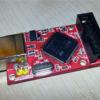
I thought about trying to fix the piggy using something like this:
But at this point I'm not sure if I trust the components installed on it anyway. Well, I should get the Rottendog DMD driver board tonight! Wish me luck :)

-Kris

Edited by antropus, 01 April 2013 - 06:25 PM.


#85 RoccoC

RoccoC

    Hobbyist

  • Members
  • PipPip
  • 43 posts
  • Location:Phoenix

  • Flag: United States of America

  • Favorite Pinball: Attack from Mars

Posted 01 April 2013 - 07:23 PM

Did you actually find damaged traces on the DMD Piggy?

UPS should be delivering the transformer sample today. I'll let you know what happens with my piggy after I wire things up.

#86 antropus

antropus

    Enthusiast

  • Platinum Supporter
  • 229 posts
  • Location:Bay Area

  • Flag: United States of America

  • Favorite Pinball: Monster Bash

Posted 01 April 2013 - 07:43 PM

No, not yet. I'll try to track where's the problem in the piggy, but I'm getting a good feeling about the rottendog board!
Good luck, man!!! :)

-Kris

#87 zebulon

zebulon

    Cantankerous old B****D

  • Platinum Supporter
  • 1,179 posts
  • Location:Whitby, Ontario, Canada

  • Flag: Canada

  • Favorite Pinball: xenon, Medieval Madness, Royal Flush, Silverball Mania

Posted 01 April 2013 - 11:38 PM

I think you'll find that there's a dead diode or transistor on that piggy Kris. I'm leaning toward a diode as the diodes used in the circuit are zener diodes and the 25v variance in voltage is just too even of a deviation. That variation makes me wonder if the 12v output on the piggy needs to connected to something (there should be a couple of 12v zeners farther down the circuit that switch the 12v output.


Be interesting to see what happens with the rottendog. I've used their rectifier boards (from Bay Area Amusements as well) in my pinball restores and they make some quality stuff.


 ZB%20%20Storefront1%20.png               [email protected]

Don't pm or expect an answer from me here ... the links above are my contacts.

I know so much about so little that I could teach you all there is to know about nothing......


#88 kruge99

kruge99

    Pinball Wizard

  • VPF Staff
  • 3,901 posts
  • Location:Markham, Ont.

  • Flag: Canada

  • Favorite Pinball: Black Knight, High Speed and Pin*Bot


Posted 01 April 2013 - 11:53 PM

I think you'll find that there's a dead diode or transistor on that piggy Kris. I'm leaning toward a diode as the diodes used in the circuit are zener diodes and the 25v variance in voltage is just too even of a deviation. That variation makes me wonder if the 12v output on the piggy needs to connected to something (there should be a couple of 12v zeners farther down the circuit that switch the 12v output.


Be interesting to see what happens with the rottendog. I've used their rectifier boards (from Bay Area Amusements as well) in my pinball restores and they make some quality stuff.


Hey Zeb, Playdium / Starburst carries some Rottendog stuff now, that's where I picked up my MPU327 for my Solar Fire actually.


Best Regards,

Todd.


Edited by kruge99, 01 April 2013 - 11:54 PM.

[proud owner of a Williams Solar Fire]

- It's called "The American Dream" because you have to be asleep to believe it.
George Carlin
- Truly great madness cannot be achieved without significant intelligence.
Henrik Tikkanen
- "Reality check, Michelle, Talk about composure, Total lack of. He's a man-- About-- 12 Feet Tall--"
Carrie Kelly
Posted Image

#89 antropus

antropus

    Enthusiast

  • Platinum Supporter
  • 229 posts
  • Location:Bay Area

  • Flag: United States of America

  • Favorite Pinball: Monster Bash

Posted 02 April 2013 - 03:09 AM

Good news and bad news :-/ Good news: the high voltages were reading correctly, at around -117.6VDC and -105.6VDC, which is really good! Bad news: again, as soon as the 14pin interface from the pinDMD2 is connected to the DMD, fuse blows instantly (slow blow fuse btw). Other than the better job done producing the correct voltages, even with the rottendog board, the original problem persists and I have no idea why :-/ I still wonder if this might be related to the ground. I tried using the other PSU to get the ground from, but another fuse bit the dust. I wonder if I should be getting the ground from the high voltage transformers instead of the computer PSU. Ideas? So frustrating... Rocco, any progress? -Kris

#90 RoccoC

RoccoC

    Hobbyist

  • Members
  • PipPip
  • 43 posts
  • Location:Phoenix

  • Flag: United States of America

  • Favorite Pinball: Attack from Mars

Posted 02 April 2013 - 03:13 AM

I received the sample transformer this afternoon and just got around to unboxing it. Man, this thing is dense! It's roughly a 4" cube but must weigh close to five pounds. The black and white leads are the 120V primary, the red leads are the 80V secondary, and the yellow leads are the 100V secondary:


2013-04-01%2019.44.59.jpg


With the primary leads connected to my wall outlet (120.2VAC) I read 113.1V on the 100V secondary and 89.7V on the 80V secondary. This is a bit high but probably to be expected since there is no load.


Next, I wired up the transformer and my ATX power supply to the appropriate inputs of the DMD piggy and took some measurements (DMD not connected):


Pin                 Voltage (VDC)      _____Nominal Voltage (VDC)_
1                      -118.4                              -125
2                      -107.6                              -113
3                      UNUSED

4                      GND

5                      GND

6                      5.2                                     5
7                      11.7                                  12
8                      64.1                                  62


In summary, it appears that all voltages are where they need to be. Kris, I guess you have a faulty board as Zebulon suggested?  :(


As I mentioned in a previous post, I don't have a PinDMD2 yet (anyone have one for sale?  :)) so I can't fully test with the display connected. As soon as I get a hold of one I will do some more thorough testing and report back. So far though, the transformer is looking like it should work.


EDIT: just saw Kris's post. Bummer about the fuse blowing!!! Any idea where the board is grounded to in your Monster Bash? Maybe Zebulon or russdx have some ideas? Or PinKitty can confirm how the ground is hooked up? Shoot, wish I had a PinDMD2 to test with...


Edited by RoccoC, 02 April 2013 - 03:34 AM.


#91 zebulon

zebulon

    Cantankerous old B****D

  • Platinum Supporter
  • 1,179 posts
  • Location:Whitby, Ontario, Canada

  • Flag: Canada

  • Favorite Pinball: xenon, Medieval Madness, Royal Flush, Silverball Mania

Posted 02 April 2013 - 03:40 AM

The ground should be being passed along with the voltages from both the high voltage board and the 5v line from the computer. Try using the 12v  that's produced by the high voltage board instead of the computer. In a real machine, the 5v logic is the only voltage that comes from outside of the dmd controller board.


Thanks for the tip Todd, I'll keep that in mind next time I need one (Xenon's done, Silverball Mania's done and once the pincab is done I'll be looking for another I'm sure...:))


Edited by zebulon, 02 April 2013 - 03:42 AM.

 ZB%20%20Storefront1%20.png               [email protected]

Don't pm or expect an answer from me here ... the links above are my contacts.

I know so much about so little that I could teach you all there is to know about nothing......


#92 antropus

antropus

    Enthusiast

  • Platinum Supporter
  • 229 posts
  • Location:Bay Area

  • Flag: United States of America

  • Favorite Pinball: Monster Bash

Posted 02 April 2013 - 03:58 AM

Zeb, so the board doesn't actually need the 12v? Should I try feeding only the 5v then?

#93 antropus

antropus

    Enthusiast

  • Platinum Supporter
  • 229 posts
  • Location:Bay Area

  • Flag: United States of America

  • Favorite Pinball: Monster Bash

Posted 02 April 2013 - 06:58 AM

Some more attempts tonight:


I was getting the 5v, 12v and ground from this little fellow at first: http://www.amazon.co...0v to 12v molex

It's a two prawn plug not a three as you can see. It creates its own ground for the 5v and 12v.


I did what Zeb suggested, running the ground from both the 5v of this little PSU and from the main ground. I also disconnected the 12v and as far as I can tell, the board doesn't generate a 12v. It still offsets the high voltages by 12v, but it doesn't generate a 12v output as expected on pin 7. It didn't work out either way, with or without the 12v. It kept blowing a fuse and it's a recurrent theme: every time I get the ground from the little PSU mixed with the common ground that feeds the power strip the 100v fuse will blow.


So I thought the fuse was blowing because the ground wasn't a common shared ground, so I decided to put this little PSU aside and use the actual computer PSU, making sure this way that all grounds are shared since they all come from the power strip and in fact, just connecting the low voltages, the common ground was now working and the 5V LED indicator was on. So I added the high voltages as well. Result: BAM!... another fuse gone.


Seems like when I have only that little external PSU providing its own ground for the 5v and 12v everything works fine, as long as I don't connect the pinDMD2, which causes the 100v fuse to blow again.


Seems like every time I introduce the common ground from the power strip the fuse blows.


It's kind of the same deal with connecting the piggy/DMD/pinDMD2 at same time and the fuse blowing instantly. Like, if the little psu is the only one providing its own ground, then I can attach both low and high voltages, plug into the DMD and it works fine, BUT, as soon as I introduce the pinDMD2 by connecting the 14pin cable, since it uses the common ground via PSU > USB, it blows the fuse instantly.


Seems like the problem lies on the way the whole thing is grounded, no? How should I ground this whole thing after all those frustrated tests? Very weird.


-Kris


Edited by antropus, 02 April 2013 - 07:06 AM.


#94 zebulon

zebulon

    Cantankerous old B****D

  • Platinum Supporter
  • 1,179 posts
  • Location:Whitby, Ontario, Canada

  • Flag: Canada

  • Favorite Pinball: xenon, Medieval Madness, Royal Flush, Silverball Mania

Posted 02 April 2013 - 12:13 PM

I'd consider testing the pindmd2 now for operation with an led display or trying it on the display in your monster bash using the power supply from the monsterbash cabinet. After repeatedly grounding the high voltage through the pindmd (which is what seems to be happening) it's possible that you've caused an issue with it. Russ would be the one to ask about how best to test the pindmd.


 ZB%20%20Storefront1%20.png               [email protected]

Don't pm or expect an answer from me here ... the links above are my contacts.

I know so much about so little that I could teach you all there is to know about nothing......


#95 zebulon

zebulon

    Cantankerous old B****D

  • Platinum Supporter
  • 1,179 posts
  • Location:Whitby, Ontario, Canada

  • Flag: Canada

  • Favorite Pinball: xenon, Medieval Madness, Royal Flush, Silverball Mania

Posted 02 April 2013 - 12:33 PM

What's happening is that you are floating the common for the 5v line. You need to ground the 5v signal to a common point with the common from the dmd controller board (not the pindmd). Eliminate the external 5v supply as that is just another floating ground to deal with, use the 5v from the computer psu that is powering the pindmd.


Run one of the black common wires from the molex plug coming off the psu to a known ground point on the dmd controller board. Keep the run as short as possible.

Run a wire from the  common on the pindmd to the same point on the controller board.


The earth or ground connection from the power strip is not the same as the ground in your circuit. In your circuit the ground is not actually ground but "common 0V", a starting point or a reference point for all of the voltages. The earth or ground of your power strip only comes into play if there is an issue on the ac side of the circuit which is isolated from the dc by the transformers.


Edited by zebulon, 02 April 2013 - 12:39 PM.

 ZB%20%20Storefront1%20.png               [email protected]

Don't pm or expect an answer from me here ... the links above are my contacts.

I know so much about so little that I could teach you all there is to know about nothing......


#96 russdx

russdx

    Pinball Fan

  • VIP
  • 1,317 posts
  • Location:Bristol UK

  • Flag: United Kingdom

  • Favorite Pinball: NBAFB

Posted 02 April 2013 - 12:57 PM

really need another led DMD / oscilloscope to check the pinDMD output (make sure its still ok)


#97 zebulon

zebulon

    Cantankerous old B****D

  • Platinum Supporter
  • 1,179 posts
  • Location:Whitby, Ontario, Canada

  • Flag: Canada

  • Favorite Pinball: xenon, Medieval Madness, Royal Flush, Silverball Mania

Posted 02 April 2013 - 01:03 PM

Here's the circuit broken down:


Attached File  DMD Broken Down Resized.png   108.71KB   50 downloads  Attached File  DMD Broken Down (2).png   256.14KB   52 downloadsAttached File  Babcock Display.png   354.6KB   36 downloads


Edited by zebulon, 02 April 2013 - 01:21 PM.

 ZB%20%20Storefront1%20.png               [email protected]

Don't pm or expect an answer from me here ... the links above are my contacts.

I know so much about so little that I could teach you all there is to know about nothing......


#98 antropus

antropus

    Enthusiast

  • Platinum Supporter
  • 229 posts
  • Location:Bay Area

  • Flag: United States of America

  • Favorite Pinball: Monster Bash

Posted 02 April 2013 - 04:56 PM

Zeb, thank you so much for putting those images together. Unfortunately I can only read one of them, the others are too tiny! :D

I'll make sure I test the pinDMD2 on the Monster Bash's DMD tonight. I didn't quite get what you said here: "Run a wire from the common on the pindmd to the same point on the controller board." What do you mean by that?

The funny thing is, I did try using the computer PSU before and it did blow the fuse with it. The only way the fuse doesn't blow with both high and low voltages fed to the DMD power board is when I use the little external PSU. Every time the low voltage from the computer PSU is put together with the high voltage from the transformers the fuse blows.

So:
1) 5v, 12v and GND from the little external PSU + high voltages from transformers feeding the display = works, BUT the fuse will blow as soon as the 14pin from the pinDMD2 is connected. In this case, there are two grounds, one from the little PSU and the other from the computer PSU.
2) 5v, 12v and GND from the computer PSU + high voltages from the transformers = fuse blows. In this case the ground should be the same, since the computer PSU also feeds the pinDMD2 USB, but even when the pinDMD2 is not connected, the simple fact that I'm using the computer PSU + high voltages still blows the fuse (??????!!!!).

I'm at work right now and I'll check at night when I get home (with another bag of fuses :) ). I'll first test the pinDMD2 to make sure the poor thing is still ok. I will also check another thing that's occurring to me now: I got two different PSUs in the cabinet, one feeding the computer motherboard and the other feeding the ZEB board. I need to check if the molex I'm using is coming from the same PSU that's feeding the computer, not the ZEB board. That way I can be 100% that the shared ground comes from the exact same source. Still not sure if that would work, because as I mentioned before, even with the pinDMD2 out of the equation, the fuse still blows any time I have the 5v being fed by the computer PSU instead of the little external PSU. Weird.

Thank you so much guys for all the help and I really hope that I or anyone else manage to make this work. It's a necessary pain I guess, so we can create some simplified documentation that will help others to avoid those mistakes.

Cheers,
-Kris

#99 Gamester

Gamester

    Enthusiast

  • Members
  • PipPipPip
  • 185 posts
  • Location:Texas

  • Flag: United States of America

  • Favorite Pinball: .

Posted 02 April 2013 - 05:18 PM

Whew, this thread is exhausting, and another demonstration of what a valuable contributor Zeb is to this community!  :)  Hope you get it working soon, Kris.  Bummer that you're having so many problems getting it to work.


Boy, after following this thread, my led dmd is seeming less and less expensive all the time...  ;)


#100 antropus

antropus

    Enthusiast

  • Platinum Supporter
  • 229 posts
  • Location:Bay Area

  • Flag: United States of America

  • Favorite Pinball: Monster Bash

Posted 02 April 2013 - 06:07 PM

If you consider the time spent so far, yes, the LED was probably much cheaper, but hopefully once things are sorted out this will be a pretty affordable solution as well.

-Kris