Jump to content


Photo
* * * * * 7 votes

Pinscape expansion board support thread


  • Please log in to reply
1103 replies to this topic

#941 mrarcade

mrarcade

    Enthusiast

  • Members
  • PipPipPip
  • 252 posts

  • Flag: United States of America

  • Favorite Pinball: Monster Bash

Posted 17 December 2021 - 05:34 AM

Built the pinscape main board tonight. Most of it anyway. Somehow when I sent the bom to mouser it didn't list the pwm ic's tlc5940nt 28 dip. They are obsolete. Other than the 2 missing ic's (and the tv power relay circuit)  the main board is complete.


Is it OK to use it without the 2 pwm ic's installed?


#942 cerimorgan

cerimorgan

    Hobbyist

  • Members
  • PipPip
  • 12 posts

  • Flag: Welsh

  • Favorite Pinball: Game of Thrones

Posted 17 December 2021 - 06:10 AM

Far from a definitive answer, but I believe the outputs will not work, but the button inputs will(?). There is a note on the "Debugging the Expansion Boards" page saying that you can only find the 5940 ICs on eBay now. It would probably be good to add that to the Electronic Part List page as well. I got some off of eBay as suggested.


#943 mrarcade

mrarcade

    Enthusiast

  • Members
  • PipPipPip
  • 252 posts

  • Flag: United States of America

  • Favorite Pinball: Monster Bash

Posted 17 December 2021 - 09:21 PM

Yeah, I went ahead and ordered five from china. I was just bummed out that apparently the bill of materials at Mouser did not show me this part was unavailable. It did on half a dozen other parts for which I had to find compatible replacements. But it did not even show the pwm chip.

Edited by mrarcade, 18 December 2021 - 04:05 PM.


#944 mrarcade

mrarcade

    Enthusiast

  • Members
  • PipPipPip
  • 252 posts

  • Flag: United States of America

  • Favorite Pinball: Monster Bash

Posted 18 December 2021 - 04:13 PM

After finishing the main board (which took me 5 hours) I looked at the finished board and thought, how did that take me so long? It doesn't look like much. Then I looked at the pile of empty parts bags and thought, that's how.
I hadn't done much soldering lately, and had never had to completely populate a board. This was an experience. I am pretty sure things will go more quickly when I build the power and chime boards, but not too fast. I am hoping that taking the time to look over each component after soldering will eliminate problems that could pop up in the future.

#945 cerimorgan

cerimorgan

    Hobbyist

  • Members
  • PipPip
  • 12 posts

  • Flag: Welsh

  • Favorite Pinball: Game of Thrones

Posted 18 December 2021 - 04:19 PM

I feel like the main board took me the longest partly because of lack of recent (20ish years!) soldering experience and partly because there were so many varied components. With the power and chime boards, there are many repeated circuits and I found it quicker to be able to solder the same component repeatedly, then move on to the next component (except for the resistors on the power board, which I learned to do in pairs because some of the through holes are so close).


Good luck!


#946 cerimorgan

cerimorgan

    Hobbyist

  • Members
  • PipPip
  • 12 posts

  • Flag: Welsh

  • Favorite Pinball: Game of Thrones

Posted 21 December 2021 - 07:14 PM

Just to follow-up on my original post from a couple of months ago, I finally put everything(-ish) together yesterday in my cabinet and all three Pinscape boards are working as expected. It had been so long since I had the issue with the knocker output from my main board that I wired up the replay knocker to it and it took a while to realize why it wasn't working. I shifted it to the chime board and it worked perfectly. Playing my first game of White Water with the real flippers, with contactors and surround sound playfield speakers was amazing!


Thanks for your invaluable build guide and all the help with debugging, MJR!


#947 mrarcade

mrarcade

    Enthusiast

  • Members
  • PipPipPip
  • 252 posts

  • Flag: United States of America

  • Favorite Pinball: Monster Bash

Posted 22 December 2021 - 05:34 AM

I am mapping out my pin to decide what I need to order for the power board and chime board. I don't plan to use all the outputs, I just want to order the components I need. I have 5 TLC5940NT on order from China, that will populate the main board and the power board.


I plan to attach to the


main board:


input buttons JP1


analog plunger JP2


knocker


strobe


5 flashers JP11


LEDs JP8

1rbg left and right flippers (5mm Piranha RGB LED in Frosted Lens forward voltage 30ma)

2rgb left magna-save (5mm Piranha RGB LED in Frosted Lens forward voltage 30ma)

3rgb right magna-save (5mm Piranha RGB LED in Frosted Lens forward voltage 30ma)

4r launch ball 555 led

4g start 555 led

4b add ball\continue 555 led

5r exit 555 led

5g lockdown bar action button 555 led

5b super game 555 led


Power Board:


red beacon

blue beacon

fan

shaker motor (future)

bell (reciprocating) future


Chime board:


chime 1

chime 2

chime 3

bell (single ring) (future)


I want to verify that I can do the cabinet led buttons on main board J8. This will work, correct?


For the power board, I will have both TLC5940NT needed. I should only have to populate 5 of the 32 channels, correct? I will likely order enough for 7 or 8 channels, but no reason to populate all 32 channels, correct?


For the chime board, I need 3 channels for a chime unit. I hope to add a bell (single ring) in the future. I should only need to populate 4 channels, correct?


#948 Stahlwolle777

Stahlwolle777

    Hobbyist

  • Members
  • PipPip
  • 11 posts

  • Flag: Germany

  • Favorite Pinball: Indiana Jones

Posted 28 December 2021 - 10:45 AM

How can Joystick-buttons be deleted in config? I use external Arcadebutton-board and want to use the unused button-inputs as outputs for solenoids...

Edited by Stahlwolle777, 28 December 2021 - 10:46 AM.


#949 mrarcade

mrarcade

    Enthusiast

  • Members
  • PipPipPip
  • 252 posts

  • Flag: United States of America

  • Favorite Pinball: Monster Bash

Posted 28 December 2021 - 08:09 PM

How can Joystick-buttons be deleted in config? I use external Arcadebutton-board and want to use the unused button-inputs as outputs for solenoids...


Edited by mrarcade, 30 January 2022 - 05:03 PM.


#950 mjr

mjr

    Pinball Wizard

  • Members
  • PipPipPipPipPip
  • 3,278 posts

  • Flag: United States of America

  • Favorite Pinball: Medieval Madness

Posted 28 December 2021 - 09:31 PM

How can Joystick-buttons be deleted in config? 


Just click the pin assignment box for the button row, and select Not Connected in the pin selector dialog.  That'll disconnect it from the GPIO and let you use the GPIO for whatever else you want to assign it to.


#951 mrarcade

mrarcade

    Enthusiast

  • Members
  • PipPipPip
  • 252 posts

  • Flag: United States of America

  • Favorite Pinball: Monster Bash

Posted 02 January 2022 - 08:01 AM

It looks like I have 8 TLC5940NT on the way. Something is through customs in China.


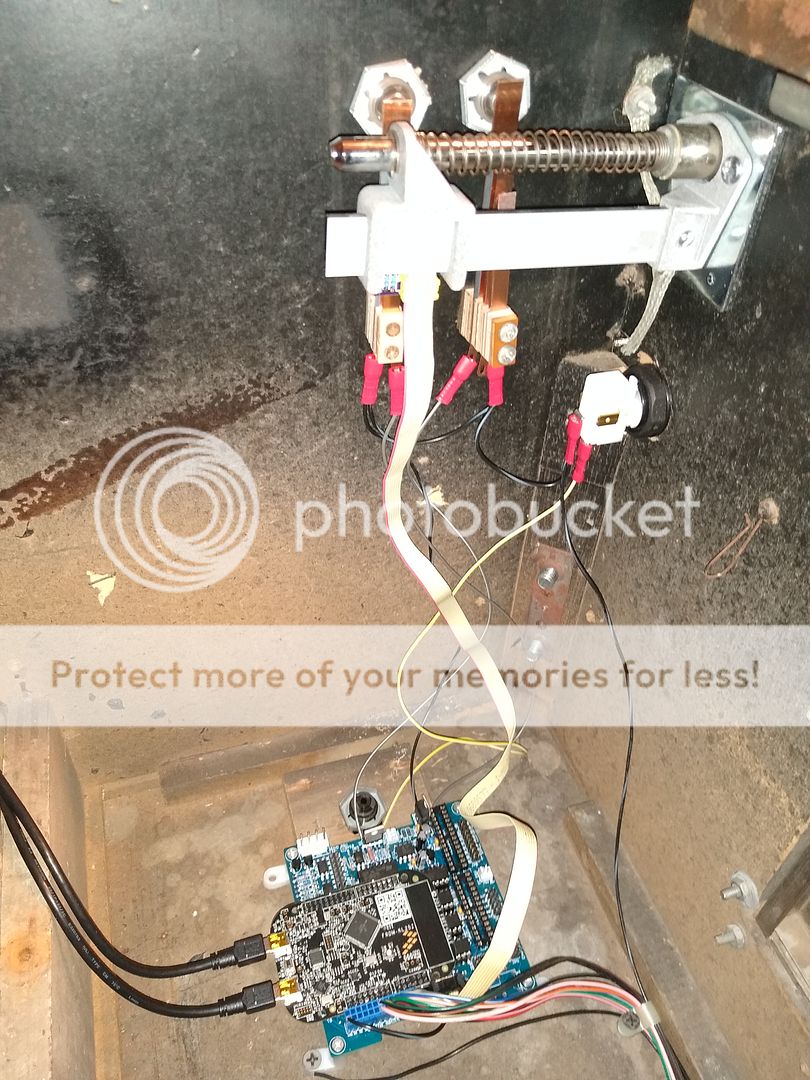
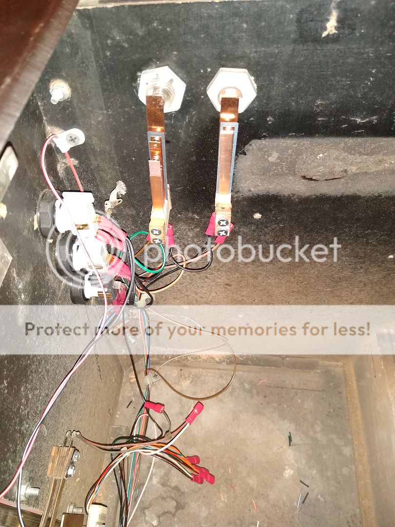
I worked on the Stellar Wars today. I finished drilling the left MS\extra flipper button.  I wired up the buttons (4 flipper, 5 front of cab, 4 setup menu in coin door, and a coin door switch. I wired up the 12v contactor  relay for the power strip(s). I wired up the 2 and 4 pin power for the pinscape main board.


I updated the KL25Z using a win7 laptop and installed it and the config tool.


I set up the buttons, might have to fiddle around a little later.


The plunger shows no sign of life. It is the AEDR-8300 Encoder. It had been sitting like I received it, assembled in the foil bag, for 4 years. I wired it up and mounted it a few days ago. I finally got to test it today, I am assuming it will work without the 2 TLC5940NT installed.


Here are some pics:


plunger-board.jpg


plunger-board2.jpg


12v-relay.jpg


pc-mounted.jpg


right-buttons-plunger.jpg


left-buttons.jpg


door-buttons.jpg


#952 mrarcade

mrarcade

    Enthusiast

  • Members
  • PipPipPip
  • 252 posts

  • Flag: United States of America

  • Favorite Pinball: Monster Bash

Posted 04 January 2022 - 04:24 AM

I figured out the plunger issue, the ribbon connector on the plunger board was only connecting 1 conductor. I trimmed the base so the knives would penetrate more and it works now.


#953 mrarcade

mrarcade

    Enthusiast

  • Members
  • PipPipPip
  • 252 posts

  • Flag: United States of America

  • Favorite Pinball: Monster Bash

Posted 19 January 2022 - 05:02 PM

I ordered 1K9 resistors thinking they were 1K resistance. They are 1.9K. Any chance the 1.9K will work instead of 1K for the power board and chime board, Or do I need to get 1K resistors? Also, I am not fully populating the power board. I am putting in opto coupler one two and three, so then I am planning to populate q1a through q3D along with associated resistors. Is that correct?

Thanks again for all your help. I have been having fun playing the pinball with my daughter. Looking forward to getting the toys working.


Edited by mrarcade, 24 January 2022 - 02:22 AM.


#954 mjr

mjr

    Pinball Wizard

  • Members
  • PipPipPipPipPip
  • 3,278 posts

  • Flag: United States of America

  • Favorite Pinball: Medieval Madness

Posted 19 January 2022 - 07:29 PM

> Any chance the 1.9K will work instead of 1K for the power

> board and chime board, Or do I need to get 1K resistors?


I think those should work okay.  Higher resistance will slow down the MOSFET switching time, which could conceivably affect the range of achievable PWM duty cycles, but I think everything is fast enough that it won't matter in this context.  But I haven't tested with other values, so I can't say for sure.


> Also, I am not fully populating the power board.


That should be fine as well.  I've seen a things on the Web suggesting that TLC5940 chips can have problems if you leave outputs unloaded, but I haven't seen any problems with it in practice (that's something I have tested with), and I don't think the TI data sheet has any warnings about it.


#955 mrarcade

mrarcade

    Enthusiast

  • Members
  • PipPipPip
  • 252 posts

  • Flag: United States of America

  • Favorite Pinball: Monster Bash

Posted 24 January 2022 - 06:48 AM

I finally started testing dof. Not having any luck. I am afraid the pwm ics from china are bad. nothing but input buttons and nudge will work. Strobe will light when - is hooked to pwm -, not with strobe pin. same with small led, they will light when I hook direct to -, but not through any jp8 pin. flashers are the same. I am testing with a 3 led 5v pushbutton lamp. Oddly it was much brighter when hooked to small led than when hooked to flasher. hook direct to - and I get dim led. nothing through the flasher pins.


When I tested the knocker (with diode, + to banded end) it worked once and the psu I hoped would work went into shutdown, It only has 1.8a available for 48v. I turned the knocker off and reset the psu. The knocker seemed stuck on, when I plugged the psu back in the knocker would fire even though it was set to OFF in the config tool.


Is the strobe controlled by a pwm ic? If not, I will have to inspect my soldering etc again.


Up too late, time to sleep.


#956 mjr

mjr

    Pinball Wizard

  • Members
  • PipPipPipPipPip
  • 3,278 posts

  • Flag: United States of America

  • Favorite Pinball: Medieval Madness

Posted 24 January 2022 - 09:19 PM

The strobe port does go through the TLC5940 - IC1 pin 15.


The knocker symptoms sound like you might have overloaded the MOSFET.  "Stuck on" usually means that the MOSFET is shorted internally, which seems to be a common way they fail.  There are other failure modes that could cause the same thing, but if you use a multimeter to measure resistance between the MOSFET drain and source (Q1 pins 2 and 3, the pair on the opposite side from JP9) and you read something small, like 0 ohms or 4 ohms, the MOSFET is probably dead.  It sounds like you had it properly protected with the diode, so I'm not sure what could have happened, but maybe it was some kind of interaction with the power supply when it went into overload.  If you test the knocker with just the power supply (without the expansion board in the circuit), does that also trigger the overload shutdown?  I'm guessing it probably will, since the standard AE-26-1200 knocker coil has about 11 ohms of DC resistance, so at 48V it will want to draw about 4.5A, way over the 1.8A rating you mentioned.  Assuming you're using an SMPS for the 48V supply, you should probably get something rated even higher than the nominal coil draw, maybe 150% of the max current draw, since SMPS's as a class aren't great at delivering big spikes of power on demand.  48V SMPS's that beefy can be expensive, so a lot of people use lower-voltage supplies with the replay knockers to save some money, like 24V.  Most people seem to be satisfied with the loudness even at the lower voltage.  So you might consider that if you have trouble finding a reasonably priced 48V supply that's beefy enough.


If you haven't already gone through the board debugging chapter in the build guide, you might try the steps there to see if there's a bad connection to the TLC5940 control lines.  The chips won't work at all if even one of the control signals is missing, so in a lot of cases, a board that seems completely dead can be fixed by finding and fixing one bad solder joint.  If you have spares of the TLC5940 chips and you socketed them, an easy first thing to try is to swap in some of the spares to see if one of them works.  Or just swap the two TLC5940 chips currently in the board - you could have one bad chip and one bad solder joint on the other chip.  I always like to try the easy and quick and non-invasive tests like that first before starting the long slot of testing continuity point by point.


#957 mrarcade

mrarcade

    Enthusiast

  • Members
  • PipPipPip
  • 252 posts

  • Flag: United States of America

  • Favorite Pinball: Monster Bash

Posted 25 January 2022 - 11:29 PM

ok, I screwed up with the knocker. I thought it was a 50v. It only has 5 ohms resistance, so that would be 10 amps at 50v. I am guessing it should be 24v, that would be 4.8 amps. I will have to see if I ruined something on the main board hitting that circuit with around 10 amps..


I don't see a short on Q1. What else is in the circuit?


Edited by mrarcade, 26 January 2022 - 01:00 AM.


#958 mjr

mjr

    Pinball Wizard

  • Members
  • PipPipPipPipPip
  • 3,278 posts

  • Flag: United States of America

  • Favorite Pinball: Medieval Madness

Posted 26 January 2022 - 12:52 AM

> I thought it was a 50v. It only has 5 ohms resistance, so that would be 10 amps at 50v.


Yeah, that's probably a little more power than you need, unless you want to knock a hole through the plywood.  I expect it'll still be quite powerful at 24V - 12V might even be enough.  Depending on which MOSFET you used, 10A would probably be safe as far as that goes, but I'm more concerned about the transient voltage when the power supply went into overload.  In any case, the MOSFET is at the front line in these situations, so it's the most likely thing to get damaged.  Voltage spikes can sometimes penetrate into the circuit beyond the MOSFET, but that doesn't seem to happen a lot - usually you just get a shorted (stuck "on") MOSFET.


#959 mrarcade

mrarcade

    Enthusiast

  • Members
  • PipPipPip
  • 252 posts

  • Flag: United States of America

  • Favorite Pinball: Monster Bash

Posted 26 January 2022 - 02:34 AM

I swapped in both other pair of TLC5940NT's. Small LEDs etc still not working. 


Q1 does not show a short.

I get 128 ohm with the black lead on pin 2, red lead on pin 3, and 158 ohm with the black lead on pin 3, red lead on pin 2 of Q1.


The FET is:


Mouser #: 512-FQP13N06L


Mfr. #: FQP13N06L Desc.: MOSFET MOSFET 60V N-Channel QFET Logic Level


Edited by mrarcade, 26 January 2022 - 03:06 AM.


#960 mjr

mjr

    Pinball Wizard

  • Members
  • PipPipPipPipPip
  • 3,278 posts

  • Flag: United States of America

  • Favorite Pinball: Medieval Madness

Posted 26 January 2022 - 05:13 AM

> Q1 does not show a short.
> I get 128 ohm with the black lead on pin 2, red lead on pin 3, and
> 158 ohm with the black lead on pin 3, red lead on pin 2 of Q1.
 
I'm afraid that does count as a short when we're talking about a MOSFET drain-source measurement - the resistance across those pins should be basically infinity (in the high meg-ohms) when the device is off.  Readings can sometimes be confounded when you take them in situ, but in this case I don't think there's anything else there that would throw off the reading.

The FQP13N06L is rated for 13.6A continuous, so in principle 10A shouldn't damage it.  Its max voltage is 60V, which should also be fine for a 48V supply, but who knows what happened to current and voltage during the power supply cut-out.  MOSFETs are particularly sensitive to voltage.  It's also possible that the device was DOA - did the solenoid firing and power supply cutout occur as soon as you connected power, or was everything okay until you deliberately activated the output port through the software?


Edited by mjr, 26 January 2022 - 05:15 AM.