Jump to content


Photo
* * * * * 7 votes

Pinscape expansion board support thread


  • Please log in to reply
1103 replies to this topic

#861 mjr

mjr

    Pinball Wizard

  • Members
  • PipPipPipPipPip
  • 3,331 posts

  • Flag: United States of America

  • Favorite Pinball: Medieval Madness

Posted 16 February 2021 - 05:50 AM

Dumb question. Is it possible to assemble only half of the power and chime expansion boards? I only need 14 power outputs and 3 chime outputs for all of my toys. Is it as simple as omitting the circuit parts on the outputs? In other words, a "side" of the power board mosfet/resistor/capacitor bank then half of the timer/power circuits/mosfets on the chime board and leaving all the other supporting circuits to power the boards? Or, does that require an electrical adjustment somewhere or cause issues that might throw off how the IC's handling addressing? TIA.


Not a dumb question at all.  Yes, both boards will work if partially built.  In the case of the chime board, there's a little box drawn around each output circuit unit, so you can leave out any of the units by omitting all of the parts within its box.  There's a diagram in the build guide showing how the boxes correspond to output pins, under Bypassing the timers on the chime board, here:


http://mjrnet.org/pi...d=expanAssembly


You can also omit the MOSFET for each timer circuit you skip.  Hopefully that makes sense.  You do need to populate all of the rest of the parts (the ones not enclosed in the output unit boxes), since the rest is all shared.


For the power board, you can populate it in halves.  The physical layout matches the electrical layout pretty closely, so it should be pretty clear what a "half" is just looking at it.  You basically need the TLC5940NT chip and the four PC847 chips for each half to populate that half.  So you can leave one TLC5940NT chip and the adjacent four PC847 chips out if you only need half the circuits.  You can also choose to populate the MOSFET circuits individually on the built half, so you could build a half-board with, say, only 11 outputs rather than all 16.  Just leave out the MOSFET and the adjacent two resistors for each circuit you don't need.


Edited by mjr, 16 February 2021 - 05:51 AM.


#862 sirwoogie

sirwoogie

    Hobbyist

  • Members
  • PipPip
  • 23 posts
  • Location:Michigan

  • Flag: United States of America

  • Favorite Pinball: Addams Family

Posted 16 February 2021 - 05:52 PM

Perfect, that is what I thought the answer would be.


Suggestion for a new board design, make one half direct power (for 16) and second half with timers (4). That'd get you enough room for all the typical toys and providing safety for chimes and a bell. :)


#863 bigfoot53

bigfoot53

    Hobbyist

  • Members
  • PipPip
  • 25 posts

  • Flag: United States of America

  • Favorite Pinball: BlackKnight

Posted 19 February 2021 - 09:51 PM

Evening Everyone,

Finally got around to assembling my power board and am having issues  :) Nothing works i get no outputs at all  . i have checked and switched the tlc549nt chips from the main board, checked all 10 pins on the interconnect cable. still nothing.

I have checked the expansion boards option in the software  is there something else i need to configure ?  also updated to the latest firmware.


also is it possible to have the main board turn on the second psu  ?


Thanks

Bruce


#864 mjr

mjr

    Pinball Wizard

  • Members
  • PipPipPipPipPip
  • 3,331 posts

  • Flag: United States of America

  • Favorite Pinball: Medieval Madness

Posted 19 February 2021 - 10:29 PM

Finally got around to assembling my power board and am having issues  :) Nothing works i get no outputs at all  . i have checked and switched the tlc549nt chips from the main board, checked all 10 pins on the interconnect cable. still nothing.

I have checked the expansion boards option in the software  is there something else i need to configure ?  


As part of that, you set "Number of power boards" to 1, right?  And you set up the new outputs in the Output Ports list?


That should be all that's necessary on the configuration side, so if it's still not working after that, it's probably a hardware problem.  Have you gone through the steps in the Initial Testing and Debugging chapters?


http://mjrnet.org/pi...p?sid=expanTest

http://mjrnet.org/pi...?sid=expanDebug


Hopefully it'll get it working if you carefully go through the steps and tests there.


also is it possible to have the main board turn on the second psu  ?


No, I'm afraid there's no provision for that.  You need to rig something separate for that.  There are a few common approaches people use, and they're mostly pretty simple to implement.  Details in the Power Switching section:


http://mjrnet.org/pi...=powerSwitching


#865 bigfoot53

bigfoot53

    Hobbyist

  • Members
  • PipPip
  • 25 posts

  • Flag: United States of America

  • Favorite Pinball: BlackKnight

Posted 19 February 2021 - 11:15 PM


Finally got around to assembling my power board and am having issues  :) Nothing works i get no outputs at all  . i have checked and switched the tlc549nt chips from the main board, checked all 10 pins on the interconnect cable. still nothing.

I have checked the expansion boards option in the software  is there something else i need to configure ?  


As part of that, you set "Number of power boards" to 1, right?  And you set up the new outputs in the Output Ports list?


That should be all that's necessary on the configuration side, so if it's still not working after that, it's probably a hardware problem.  Have you gone through the steps in the Initial Testing and Debugging chapters?


http://mjrnet.org/pi...p?sid=expanTest

http://mjrnet.org/pi...?sid=expanDebug


Hopefully it'll get it working if you carefully go through the steps and tests there.


also is it possible to have the main board turn on the second psu  ?


No, I'm afraid there's no provision for that.  You need to rig something separate for that.  There are a few common approaches people use, and they're mostly pretty simple to implement.  Details in the Power Switching section:


http://mjrnet.org/pi...=powerSwitching


Yes set to 1  how do i setup the outputs ? that could be the issue :)


Thinking of trying this for the second psu power up.


https://www.amazon.c...IJD0C8L78&psc=1


Has anyone else used one of these ? If so does it work ok?


Bruce


#866 mjr

mjr

    Pinball Wizard

  • Members
  • PipPipPipPipPip
  • 3,331 posts

  • Flag: United States of America

  • Favorite Pinball: Medieval Madness

Posted 19 February 2021 - 11:29 PM

Yes set to 1  how do i setup the outputs ? that could be the issue :)


The ports should have been automatically added when you added the power board to the configuration.  Just scroll down to the Output Ports list in the settings page to verify that you see the 32 outputs for the power board.


Thinking of trying this for the second psu power up.

https://www.amazon.c...IJD0C8L78&psc=1


That might do the trick, if you don't need to tap into the main 24-pin connector from the secondary, *and* if you don't need to control power to anything besides the secondary PSU.  Most people want to control power to their TVs, audio amplifiers, and so on, which is why most people use the smart power strip or switched power strip approach.


#867 bigfoot53

bigfoot53

    Hobbyist

  • Members
  • PipPip
  • 25 posts

  • Flag: United States of America

  • Favorite Pinball: BlackKnight

Posted 19 February 2021 - 11:40 PM


Yes set to 1  how do i setup the outputs ? that could be the issue :)


The ports should have been automatically added when you added the power board to the configuration.  Just scroll down to the Output Ports list in the settings page to verify that you see the 32 outputs for the power board.


Thinking of trying this for the second psu power up.

https://www.amazon.c...IJD0C8L78&psc=1


That might do the trick, if you don't need to tap into the main 24-pin connector from the secondary, *and* if you don't need to control power to anything besides the secondary PSU.  Most people want to control power to their TVs, audio amplifiers, and so on, which is why most people use the smart power strip or switched power strip approach.


yep i have all 32 listed but if i turn any of the connected ones on i get no output.


#868 starcommand79

starcommand79

    Neophyte

  • Members
  • Pip
  • 2 posts

  • Flag: ---------

  • Favorite Pinball: Jokerz

Posted 19 February 2021 - 11:41 PM

It looks like there's only one ground connection for the 12V power but everywhere I read says there's two connections? What am I missing here?


#869 mjr

mjr

    Pinball Wizard

  • Members
  • PipPipPipPipPip
  • 3,331 posts

  • Flag: United States of America

  • Favorite Pinball: Medieval Madness

Posted 20 February 2021 - 01:32 AM

yep i have all 32 listed but if i turn any of the connected ones on i get no output.


You'll probably want to go through those setup/debugging chapters I linked above.  Sounds like you might have something wrong in the hardware.


It looks like there's only one ground connection for the 12V power but everywhere I read says there's two connections? What am I missing here?


Not sure what we're talking about here - could you be more specific?  Ground connections where, read what?


#870 bigfoot53

bigfoot53

    Hobbyist

  • Members
  • PipPip
  • 25 posts

  • Flag: United States of America

  • Favorite Pinball: BlackKnight

Posted 20 February 2021 - 02:18 AM

i'll re check everything and see what i can find :)


Thanks


Bruce


Edited by bigfoot53, 20 February 2021 - 02:18 AM.


#871 bigfoot53

bigfoot53

    Hobbyist

  • Members
  • PipPip
  • 25 posts

  • Flag: United States of America

  • Favorite Pinball: BlackKnight

Posted 20 February 2021 - 06:10 PM

Issue resolved :)  Had a bad 3.3v Regulator  Guess i got a defective one  but happen to have a spare .


Thanks

for all the help

 Now on to setting up dof  Any tips for setting it up ?


Bruce


#872 mjr

mjr

    Pinball Wizard

  • Members
  • PipPipPipPipPip
  • 3,331 posts

  • Flag: United States of America

  • Favorite Pinball: Medieval Madness

Posted 20 February 2021 - 07:39 PM

Issue resolved :)  Had a bad 3.3v Regulator  Guess i got a defective one  but happen to have a spare .


Great, glad you were able to track it down!


Now on to setting up dof  Any tips for setting it up ?


http://mjrnet.org/pi...ide.php?sid=DOF


You can also find per-device DOF setup notes in the chapters about the individual feedback devices - look for the "DOF Setup" topic in each one.


http://mjrnet.org/pi...sid=buttonLamps

http://mjrnet.org/pi...hp?sid=flashers


etc...


#873 sirwoogie

sirwoogie

    Hobbyist

  • Members
  • PipPip
  • 23 posts
  • Location:Michigan

  • Flag: United States of America

  • Favorite Pinball: Addams Family

Posted 25 February 2021 - 01:54 AM

My construction woes continue. I know  many have made it work, but I just keep getting stuck by many issues. My knocker... was working fine, lights up the LED and timer cuts it. Now, it doesn't light the LED at all. I check a 5V source and I see the voltage crosses on the pin (say 1.4 V), so I have no idea why the LED doesn't light. I figured I have to just scrap it and use a pin on the chime board.


Power board, I can never get my IDC cable to show anything happening on the board, so I used 10 dupont cables to build the data connection. Most of my pins (3 of the 16 are dead) the LED stays lit continuously. This is with the output tester on or off, slider up or down. I've not seen in the debug instructions on what might cause that. Ideas?


I think I'm about to throw in the towel.


Edited by sirwoogie, 25 February 2021 - 02:53 AM.


#874 mjr

mjr

    Pinball Wizard

  • Members
  • PipPipPipPipPip
  • 3,331 posts

  • Flag: United States of America

  • Favorite Pinball: Medieval Madness

Posted 25 February 2021 - 03:30 AM

My construction woes continue. I know  many have made it work, but I just keep getting stuck by many issues. My knocker... was working fine, lights up the LED and timer cuts it. Now, it doesn't light the LED at all. I check a 5V source and I see the voltage crosses on the pin (say 1.4 V), so I have no idea why the LED doesn't light. I figured I have to just scrap it and use a pin on the chime board.


Power board, I can never get my IDC cable to show anything happening on the board, so I used 10 dupont cables to build the data connection. Most of my pins (3 of the 16 are dead) the LED stays lit continuously. This is with the output tester on or off, slider up or down. I've not seen in the debug instructions on what might cause that. Ideas?


I think I'm about to throw in the towel.


I take it you've gone through the Debugging chapter and checked everything there?  It's to guess at the cause based on the symptoms alone, except that the distinction between "no outputs are working" vs "some outputs are working and some aren't" tells you whether the problem is most likely to be in the individual output stages or in the main logic section.  I'm not sure which it is from what you said here, so maybe getting a systematic read on that would be a next step.


You might also want to see if you can get the ribbon cable working.  The data connection between the boards has a rather high-speed signal (in the MHz), and the TLC5940 data protocol is quite primitive and is very sensitive to noise on those lines.  Your entire problem might be that you're not getting a clean enough connection with the Dupont wires.  The #1 thing I'd check with the ribbon cable is that you've got PIN 1 connected to the same wire on both sides - it's really easy to get that thing rotated 180 degrees on one or the other end.  I always take a red permanent marker and draw a stripe down one edge of the cable from end to end, and make sure the stripe is aligned with the PIN 1 arrow printed on the board.  If you're absolutely sure that the PIN 1 orientation is correct on both ends, I'd maybe get out a pair of pliers and give the ends a good squeeze (carefully, don't break it) to make sure all of the pins are properly seated.


#875 sirwoogie

sirwoogie

    Hobbyist

  • Members
  • PipPip
  • 23 posts
  • Location:Michigan

  • Flag: United States of America

  • Favorite Pinball: Addams Family

Posted 25 February 2021 - 03:55 AM

I take it you've gone through the Debugging chapter and checked everything there?  It's to guess at the cause based on the symptoms alone, except that the distinction between "no outputs are working" vs "some outputs are working and some aren't" tells you whether the problem is most likely to be in the individual output stages or in the main logic section.  I'm not sure which it is from what you said here, so maybe getting a systematic read on that would be a next step.


Yeah, I'll go through and figure out via the debug steps you have on the pins that are dead which I'm sure is just bad connections somewhere in the circuit. What I don't understand is why all the inputs that are "good" the LED is simply illuminated no matter the state of the output in the software.


It might be as you say that the data connection is poor and that is the cause? I've verified I had pin 1 correct on each. What I've found is whatever mouser sent me for the IDC ends doesn't mesh well with the ribbon cable I have. I've verified the pitch is good, I just can't seem to get a verifiable "cable is crimped"and I don't really know a way to test them anyway. Used pliers and attempted to get a snug fit without causing breakage.

I may just have to resort to getting a bag of pre-made from amazon.

Any thought on my knocker issue? The LED no longer lights, but I can verify that voltage difference occurs when the output is on, and the timer shuts it at 2s. What I don't see though is 5V when I use a +5V header (flasher). I see 1.4V. Did something go bad in the circuit? I have no idea on how to test for something like that.


Edited by sirwoogie, 25 February 2021 - 03:55 AM.


#876 mjr

mjr

    Pinball Wizard

  • Members
  • PipPipPipPipPip
  • 3,331 posts

  • Flag: United States of America

  • Favorite Pinball: Medieval Madness

Posted 25 February 2021 - 06:31 AM

Any thought on my knocker issue? The LED no longer lights, but I can verify that voltage difference occurs when the output is on, and the timer shuts it at 2s. What I don't see though is 5V when I use a +5V header (flasher). I see 1.4V. Did something go bad in the circuit? I have no idea on how to test for something like that.


I'm not sure the wiring you're talking about looks like when you say "the LED" and "+5V header (flasher)".  Maybe you could post a wiring diagram showing what you're doing in each case?


#877 sirwoogie

sirwoogie

    Hobbyist

  • Members
  • PipPip
  • 23 posts
  • Location:Michigan

  • Flag: United States of America

  • Favorite Pinball: Addams Family

Posted 25 February 2021 - 01:03 PM

Sorry, I may not be using the right terminology.

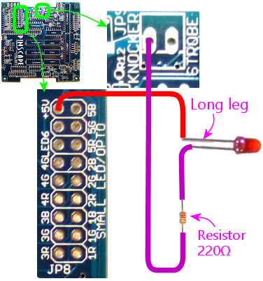
  • I use the initial debugging steps you outline with a LED+220 ohm resistor.
  • I use the +5V pin on the flasher LED bank of pins and wire the long leg of the test LED to it.
  • I verify that the LED works by enabling other flasher and small LED pins and it lights as I touch those various pins. It is bright.
  • I then check the knocker output with that LED and it doesn't light when I click the button on the output test.
  • This used to work and would light for 2 seconds and shut off as expected. Now it doesn't turn on.
  • I check the knocker pin with a multimeter and touch the positive to the +5V flasher pin and the common to the knocker pin and activate.
  • I see a 1.4V across on the multimeter for 2 seconds and then goes to zero.


Should I not be seeing 5V?


#878 mjr

mjr

    Pinball Wizard

  • Members
  • PipPipPipPipPip
  • 3,331 posts

  • Flag: United States of America

  • Favorite Pinball: Medieval Madness

Posted 25 February 2021 - 08:00 PM

sirwoogie - those all sound like reasonable basic tests.  A couple of questions and suggestions:


1. Suggestion: It sounds like you have two separate things to debug here - the power board, and the chime board.  I'd pick one and focus on exclusively that until it works.


2. Observation: For the chime board, you say it was working correctly before, and isn't working now.  I'd actually consider that a positive sign; there are a million and one ways for things to be wrong, but only one way for it to work, so getting it into that working state once means a lot of things all went right.  And it also means that all of the component parts were working at one point.  Whatever's wrong has to be a change between when it was working and now.


3. Question: Following up on #2, trying to think of what could have changed for the chime board, do you have any reason to suspect foul play?  Like, maybe you accidentally connected +50V to something you shouldn't have, or short-circuited one of the pins?  If so, it would be reasonable to suspect a dead or damaged part.  If nothing like that ever happened, given that the board was working in the past, there's little reason to suspect a bad part - it's not impossible, it's just unlikely, since electronic components that aren't outright DOA and aren't subjected to some kind of overload usually last for a long time.  So if you don't suspect foul play, I'd focus on the simpler more basic things, like cable/pin connections and solder joints.  I can't emphasize enough how easy it is for a bad solder joint to occur.  And they're often invisible to the eye, which is why I think it's pretty much a requirement to do continuity testing with a multimeter as one of the first debugging steps.


4. That 1.4V reading on the multimeter does suggest that the chime board output is activating.  That reading matches the voltage drop I'd expect for an LED.  Dumb question, but you've tested the LED just with the 5V power source directly to make sure the LED itself is working?  Maybe try another LED, just to be extra sure?


5. And another dumb question, but all of the power and ground inputs to the chime board are connected, right?


Edited by mjr, 25 February 2021 - 08:03 PM.


#879 sirwoogie

sirwoogie

    Hobbyist

  • Members
  • PipPip
  • 23 posts
  • Location:Michigan

  • Flag: United States of America

  • Favorite Pinball: Addams Family

Posted 25 February 2021 - 09:05 PM

I'll stay on my topic of knocker. I still have my power board issue, but I've ordered some pre-made 10-pin IC cables and will debug that when they arrive and we can then go from there.


So....
 

I should have been a little more explicit. I have not constructed the chime board yet. The knocker circuit I am referring to is the main board. I thought that if I couldn't get it to work, I'd just abandon the main board circuit and use a pin off the chime board. I'd rather get it working on the main board. :)


In responding to your numbers:

3. No foul play. I never used anything more than  5V source from the LEDs to test it. No high voltage used nor did I ever short it. I've looked at the soldering pads and they all look good. The issue with the knocker as you point out in the debugging instructions is that it's a somewhat complicated circuit and I'm not really able to follow the schematic to perform the end-to-end continuity you suggest. Maybe a static buildup, but that doesn't seem like it would behave this way if that occured.

4. That reading is without anything connected beyond the multimeter aligator clips to the +5V flasher pin and the knocker pin on the main board. The LED works on every other powered pin on the main board (strobe, low output LED, flasher LED). Buttons all work as well. I  have the LED/resistor on a breadboard with two dupont cables. My general test is turn on the strobe output, test the LED (works), then move the dupont cable to the knocker pin and do the output test. LED does not light.


5. No chime board as indicated above. Yes, I've verified that the computer PS 5V output is working, and the 2nd PS (tied to other 12V/5V supplies) are working and test voltage at the pads with them connected.


Edited by sirwoogie, 25 February 2021 - 09:06 PM.


#880 mjr

mjr

    Pinball Wizard

  • Members
  • PipPipPipPipPip
  • 3,331 posts

  • Flag: United States of America

  • Favorite Pinball: Medieval Madness

Posted 25 February 2021 - 10:59 PM

sirwoogie - got it, that all sounds like you're doing the right things.  Static discharge isn't too likely, but it's not impossible; MOSFET are definitely static-sensitive. 


I'm not sure how to interpret the voltmeter test on the chime board with that wiring - it's just +5V to voltmeter red and chime to voltmeter black, and nothing else connected?  And you read 0V base state, and 1.4V for a couple of seconds when you trigger the output in the config tool?  That seems wrong, because the MOSFET drain should basically drop to ground when it's on, so I'd expect it to read 5V.  But the voltmeter is such a high-resistance load that I'm not sure what to expect there.  What you might want to try is wiring something like this:


+5V ------  1K resistor ------ KNOCKER OUT


... and then measuring the voltage by connecting voltmeter RED to the wire between RESISTOR and KNOCKER OUT, and connecting voltmeter BLACK to ground.  What you should see then is +5V base state, and close to 0V when the knocker is triggered (for the two seconds it's activated before the timer cuts it, then back to 5V).


At any rate, the fact that you see the voltage change for the two second period is highly encouraging - it says to me that everything else in the timer circuit is working, and the only thing that might not be working is the MOSFET.  Because you wouldn't see a nice consistent two-second change of ANY kind if something in the timer circuit was broken.  Maybe take a magnifying glass to the bottom of the board where the MOSFET leads are soldered, and check that they all look solid.  Also check the solder on the header pin.