Jump to content


Photo
- - - - -

Pinscape Labs update - Plunger Sensors: A New Hope


  • Please log in to reply
71 replies to this topic

#61 dbknightx

dbknightx

    Hobbyist

  • Members
  • PipPip
  • 26 posts

  • Flag: United States of America

  • Favorite Pinball: Lord of the Rings

Posted 18 February 2020 - 03:32 AM

Hi Mike,

I would absolutely be willing to wait a few days for the possibility of further debugging - not just for myself but in case anybody ends up in my situation in the future.

What you described about the LED colors makes perfect sense and would definitely help to get to the bottom of this.

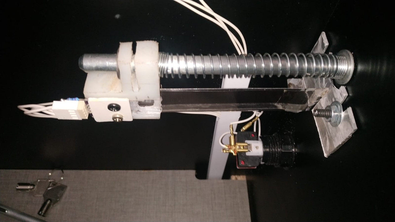
By the way my sensor is clear colored and was ordered from the Mouser link in your guide. I just double checked and it is the AEDR-8300-1K2 which is the 75 LPI version.

I will hang tight until I hear back from you. Thanks again!

#62 mjr

mjr

    Pinball Wizard

  • Members
  • PipPipPipPipPip
  • 3,323 posts

  • Flag: United States of America

  • Favorite Pinball: Medieval Madness

Posted 18 February 2020 - 09:42 PM

dbknightx - I just posted an update that adds visualization for the quadrature sensor.  I realized I should just add this to the plunger sensor viewer instead of the hacky idea with the status LEDs that I was proposing earlier.  You'll need to update both the firmware and config tool software to get the new visualization - download links are at the usual place:


http://mjrnet.org/pi.../swversions.php


The new visualization is in the regular plunger viewer window.  It'll show a simulated image of the bar code scale, along with the raw "A" and "B" channel readings.  If you move the sensor very slowly across the bar, you should be able to see the individual "A" and "B" transitions.  When things are working properly, that should translate into simulated motion along the bar code in the visualization, but in your case that might look erratic - so just ignore that and pay attention to the raw "A" and "B" readings, which are highlighted in the center of the visualization.


quadraturevisualization.png


#63 MajorFrenchy

MajorFrenchy

    Enthusiast

  • Members
  • PipPipPip
  • 256 posts
  • Location:Canada

  • Flag: Canada

  • Favorite Pinball: The Flintstones

Contributor

Posted 19 February 2020 - 01:12 AM

If my TSL1410R doesnt materialize from mouser, I was planning on using the pot Slider technique. This is another great solution though MRJ!  thanks!

 
I recently made an order from mouser using mjr's parts lists and the TSL1410R is listed as pending shipment with an availability on June 26, 2017.  I also ordered the pot slider, but would prefer the optical solution.  We'll see if they're able to deliver.
Same here.

Look at you go Mjr.
Thx a million

Sent from my SM-N960W using Tapatalk

#64 dbknightx

dbknightx

    Hobbyist

  • Members
  • PipPip
  • 26 posts

  • Flag: United States of America

  • Favorite Pinball: Lord of the Rings

Posted 19 February 2020 - 04:00 AM

mjr - wow that was fast!


I just had time this evening to install this and try it out.  The result is kind of what I expected - A/B are always in lock step.  1/1 or 0/0, which results in the software thinking it is increasing no matter what.  Now I just need to figure out why they are always the same.  It seems like it has to be one of a few things:


1). Some kind of short on the board or in the wiring.  ChA and ChB don’t show any continuity, but that isn’t always conclusive.

2). A problem with the printed pattern on the transparency.  I doubt this, since I printed 10 identical copies of the pattern on a single sheet of transparency last year and the first one I used on my previous cabinet worked great.  This is just an identical copy of that so I doubt this is the problem.

3). A defective AEDR-8300.  Certainly possible, and I guess I’d just need to order another one and try it.  Fortunately I’ve still got a single spare mounting board from the set of 3 I originally bought.


Anything else you can think of that would cause the two channels to be in lock step?


Thanks again for creating this new version of the firmware and tool.  It certainly was helpful and should be of great use in diagnosing problems in the future.  I really appreciate it!


#65 mjr

mjr

    Pinball Wizard

  • Members
  • PipPipPipPipPip
  • 3,323 posts

  • Flag: United States of America

  • Favorite Pinball: Medieval Madness

Posted 19 February 2020 - 04:27 AM

dbknightx - I'm leaning towards the idea that you have a defective AEDR-8300.  The continuity test seems like it rules out a simple short circuit between the two channels - that would be my first guess otherwise. 


One more test along the same lines you might try is to measure the resistance between the A and B channels.  The continuity test will only detect a short at close to zero ohms, but since this is a low-current signal line, it might act like this if you had a tenuous bit of extra solder somewhere making a weak connection with a relatively high resistance (thousands of ohms, say).


(If all is well, I think it should read around 5.4K ohms between the A and B pins.  Let me measure it on my test setup... yep, that's it.)


And I'm sure you've already checked this, but even so, it might be worth one more check that the pin assignments in the software match the physical wiring for the A/B channel pins.  I've gone on wild goose chases myself more than once that turned out to be pin assignment problems.


This is definitely a baffling one!  


Edited by mjr, 19 February 2020 - 04:32 AM.


#66 dbknightx

dbknightx

    Hobbyist

  • Members
  • PipPip
  • 26 posts

  • Flag: United States of America

  • Favorite Pinball: Lord of the Rings

Posted 19 February 2020 - 02:19 PM

mjr- I'm measuring 5.4K ohms between the A and B pins, so that seems fine.


I've gone ahead and ordered all new parts and will build another board.  I'm going with the ribbon cable and connector board approach this time - soldering directly to the sensor board is very difficult.  I don't think that contributed to any of my issues, but I definitely want to rule that out this time.  Mouser ships quickly but I may need to wait a bit for OshPark.  I'll definitely update you on how my next attempt goes.


I'm still very interested in the viability of the Chinese pre-built boards, which I've also ordered a couple of.  I would definitely lean that way for future builds to avoid the heat gun soldering.


And not to sound like a broken record, but I cannot thank you enough mjr for Pinscape and your amazing guides.  I never would have been able to tackle my two builds without it.


#67 dopdahl

dopdahl

    Hobbyist

  • Members
  • PipPip
  • 35 posts

  • Flag: United States of America

  • Favorite Pinball: Triple Action

Posted 05 February 2021 - 11:18 PM

It seems appropriate to bring this up in this thread, even though it's a year old...


MJR, I'm having an issue with my AEDR-8300 plunger setup.  I bought the parts directly from you a couple of years ago and just got around to setting it up.  You soldered up the board and everything.


So here's what I'm seeing...  It seems that as I pull back the plunger for the first inch, there is no movement in the realtime window of the config tool.  After about an inch, it seems to kick in and start tracking.


This, of course, results in the full pullback position being a relatively low number... like 500, while the normal resting position is 300.


The other thing I've noticed is that on the push, it seems to track twice as fast as it does on the pull.  During calibration, I can easily drive the left side of the green bar out of the window in the realtime feedback window.


It sort of feels that since the behavior seems to depend on the plunger position that this is an lousy connection on one of the channels... 


Odd thing is that is only moves twice as fast on the push, not the pull.


I'm gonna double check all the wiring based on the other posts in this thread, but it sounds like the sensor itself is fine, wouldn't you agree?


Dave


Edited by dopdahl, 05 February 2021 - 11:19 PM.


#68 dopdahl

dopdahl

    Hobbyist

  • Members
  • PipPip
  • 35 posts

  • Flag: United States of America

  • Favorite Pinball: Triple Action

Posted 06 February 2021 - 01:42 PM

So, after a bit more tinkering, it looks like the sensor is fine, but the printed scale has some issues...


Visually, it looks fine, but the sensor doesn't see it that way...  Seems like perhaps the contrast is "marginal".


Printed side facing the sensor works almost perfectly, but has an issue at the extreme of pullback.  (I can shift the scale over a bit to fix this...)...


Printed side facing away from the sensor there are issues all over the place.


I'll get another scale printed, I'm sure it will fix things up.


Dave


#69 mjr

mjr

    Pinball Wizard

  • Members
  • PipPipPipPipPip
  • 3,323 posts

  • Flag: United States of America

  • Favorite Pinball: Medieval Madness

Posted 06 February 2021 - 08:29 PM

dopdahl - the scale makes sense as the culprit.  The symptoms sounded too consistent in your description to be flaky wiring - that would typically be a lot more random because the connections would make and break sporadically.  It sounds like the scale I sent you had a printing flaw, or maybe that sheet of film was a little discolored or something.  If you have any trouble finding the transparency film or a suitable printer, let me know and I can print a new one for you.


#70 dopdahl

dopdahl

    Hobbyist

  • Members
  • PipPip
  • 35 posts

  • Flag: United States of America

  • Favorite Pinball: Triple Action

Posted 06 February 2021 - 10:29 PM

Ok, thx...  I'll let you know.  I'm trying to get it together now...


#71 CainArg

CainArg

    Hobbyist

  • Members
  • PipPip
  • 21 posts

  • Flag: Argentina

  • Favorite Pinball: Fun House

Posted 20 September 2022 - 10:14 PM

Hi!

I took a pair of AliExpress boards, ana followed the guide and advices posted here and... nothing...

I made a different attachment, a virgin vinyl (unbreakable) skate with the encoder that runs over a mirror polished stainless steel where the film was placed. No 3d printed parts brackets, just brute force materials.

Failed... tested everything and, failed again!!! it just moved slightly in live plunger viewer!!!

Changed the strip to a larger scale, nothing... just about to throw the towel when.......

I read the AEDR8300 datasheet... remember I got the chinese assembled version, with the legs at bottom of course....

Nooooooo!!!!!! legs must go horizontal!!! I realized that the encoder was 90 degrees rotated!!!
so I just turn it horizontal, in my case legs pointing front and it worked!!!!!

jajjajajajajjaja!!! worked!!!!

so... billions of thanks to you MJR!!! and thanks for all of you people for your invaluable help!!!

It works like a charm!!!


Plunger.jpg


Edited by CainArg, 22 September 2022 - 09:44 PM.


#72 BladeZX

BladeZX

    Hobbyist

  • Platinum Supporter
  • 12 posts
  • Location:Ontario, Canada

  • Flag: Canada

  • Favorite Pinball: Star Wars Force Edition

  • 360 Gamer Tag: BladeZX

Posted 16 December 2024 - 05:58 PM

Is anyone selling a AEDR8300 kit with all pieces needed?

surface soldering the AEDR8300 is beyond my skill


Could I pay someone to make me a complete kit please


Edited by BladeZX, 16 December 2024 - 06:23 PM.

Cheers
Bob