Jump to content


Photo
* * * * * 7 votes

Pinscape expansion board support thread


  • Please log in to reply
1103 replies to this topic

#521 Onevox

Onevox

    VP Zealot

  • Members
  • PipPipPip
  • 269 posts
  • Location:Virginia, USA

  • Flag: United States of America

  • Favorite Pinball: The Getaway, High Speed II

Posted 15 January 2018 - 04:34 PM


Looking to expand Pinscape's capabilities, with LED strips (rectangles around the perimeters)  lighting under my cab and on the back of my backbox. I'm wondering how to hook up with just the Main board.


You'd normally run the strips off the power board, since they're fairly current-hungry.  If you do that they work like anything else, where you feed the +12V supply to the +12V terminal on the strips, and connect the R, G, and B terminals on the strips to one power board port apiece.  It's best to select contiguous ports (say, 10, 11, 12) because the DOF configurator requires the components of an RGB device to be grouped like that.


There aren't any ports on the main board that will drive these strips directly because of the high current requirements.  However, you can get one of those cheap eBay LED strip amplifiers (they go for about $1 apiece the last I looked), and control that with one of the "small LED" ports if you're not using all of those.  You connect the strip itself to the amplifier (it more or less just plugs in), you connect the amp's power connections to 12V and ground, and you connect the amp's three control lines to three "small LED" ports.  Again, you want to group them for the config tool's sake.


The LED amps are good for 4A per chanel, same as the power board.  I think that'll support about 3m of the strips, which should be enough for your purposes.


A couple of more questions, some photos attached. Main Board only. Two separate RGB connections to the small LED ports for cab and backbox.


1. If I use LED amplifiers as shown do I hook up the + wire on the main board anywhere? or disregard because the 12V amplifiers insert all the necessary voltage.


Additional off topic questions. 

2. In a rectangle undercab lighting setup, it looks like my mini amps insert 12 amps and my 60 LED 5050 strips only pull 1.2 amps per meter (sorry for incorrect technical terms), so my 39x18x39x18" rectangle wouldn't need more than about 4 amps total and one amplifier would cover it. Does it help or hurt to insert another at the halfway point in the chain?

3.  Can I daisy chain the 12V supply from my secondary PSU to the cab LED amp to the BB LED amp? Or I must run separate lines from the PSU?


Thanks once again.  Pete

Attached Files


Edited by Onevox, 15 January 2018 - 04:41 PM.

_____________________


My build: The Joker Poker.

http://www.vpforums....showtopic=37574


#522 mjr

mjr

    Pinball Wizard

  • Members
  • PipPipPipPipPip
  • 3,331 posts

  • Flag: United States of America

  • Favorite Pinball: Medieval Madness

Posted 15 January 2018 - 06:20 PM

> 1. If I use LED amplifiers as shown do I hook up the + wire on the main board

> anywhere? or disregard because the 12V amplifiers insert all the necessary voltage.


You don't need to connect the + wire to the boards - just connect it to your +12V power supply directly


> my 39x18x39x18" rectangle wouldn't need more than about 4 amps total and one

> amplifier would cover it. Does it help or hurt to insert another at the halfway point

> in the chain?


I can't see how it would do any harm, but it's probably not necessary either as long as you're under the limit.  If you're close to the 4A limit, it might be worthwhile to avoid stressing the amps.  Most electronics are rated very conservatively, meaning the stated limits are well under the "real" limits where things will start overheating, but I'm not sure that's necessarily true of these cheap no-brand eBay parts.


> Can I daisy chain the 12V supply from my secondary PSU to the cab LED

> amp to the BB LED amp? Or I must run separate lines from the PSU?


Daisy-chaining should be completely fine.  Just consider the combined amperage and make sure you use thick enough wire.  You can find charts and calculators for that easily on the Web - here's one good table:


https://www.powerstr...m/Wire_Size.htm


If you go with 20 AWG, you'll be good to 11A.


#523 yagesz

yagesz

    Enthusiast

  • Platinum Supporter
  • 303 posts
  • Location:Wyoming

  • Flag: United States of America

  • Favorite Pinball: TAF, TSPP, Metallica, CV

Posted 15 January 2018 - 07:38 PM

> .


Why does my pinscape lag when the shaker runs. The pinscape completely freezes and I lose all my controls

#524 mjr

mjr

    Pinball Wizard

  • Members
  • PipPipPipPipPip
  • 3,331 posts

  • Flag: United States of America

  • Favorite Pinball: Medieval Madness

Posted 15 January 2018 - 10:06 PM

Why does my pinscape lag when the shaker runs. The pinscape completely freezes and I lose all my controls


I'm afraid I don't have any guesses - I haven't heard of that symptom before.   Some questions/things to try:


- Could you be more specific about what "completely freezes" means?


   - Permanently crashes the computer so you have to reboot

   - Crashes the Pinscape config tool so you have to exit and restart it

   - Something else?


- Is it ONLY the shaker that does this?


- How exactly is the shaker attached to Pinscape (expansion boards, other booster?)


- Do you have enough power for it? 


- Do you have diodes installed properly for it?


- Try disconnecting the motor and triggering the port.  Does the problem still happen?


- Try moving swapping ports with a device that's NOT causing the problem.  Trigger the devices.  Does the problem stay with the port, or does it happen with the shaker regardless of which port you're using?


Edited by mjr, 15 January 2018 - 10:06 PM.


#525 yagesz

yagesz

    Enthusiast

  • Platinum Supporter
  • 303 posts
  • Location:Wyoming

  • Flag: United States of America

  • Favorite Pinball: TAF, TSPP, Metallica, CV

Posted 15 January 2018 - 10:59 PM

Why does my pinscape lag when the shaker runs. The pinscape completely freezes and I lose all my controls


I'm afraid I don't have any guesses - I haven't heard of that symptom before.   Some questions/things to try:
 
- Could you be more specific about what "completely freezes" means?
 
The slider jumps. It won’t move fluidly.
If I play jpark the shaker will shake. The led on pinscape goes red. Flippers stick in position. When shaker stops everything goes back to normal.


   - Permanently crashes the computer so you have to reboot

No
   - Crashes the Pinscape config tool so you have to exit and restart it
   - Something else?
No. Super slow. Pinscape has closed once.
 
- Is it ONLY the shaker that does this?
 
Contactors will try momentarily

- How exactly is the shaker attached to Pinscape (expansion boards, other booster?)
 
Expansion. 12v to motor. Diode between poles on motor. Stripe on positive. Negative goes to board.

- Do you have enough power for it? 

Yes. Easily.
 
- Do you have diodes installed properly for it?

14n001. Between poles. Stripe on positive side
 
- Try disconnecting the motor and triggering the port.  Does the problem still happen?
 
Swapped ports. It persists. Nothing Connected works fine

- Try moving swapping ports with a device that's NOT causing the problem.  Trigger the devices.  Does the problem stay with the port, or does it happen with the shaker regardless of which port you're using?


Sent from my iPhone using Tapatalk

#526 yagesz

yagesz

    Enthusiast

  • Platinum Supporter
  • 303 posts
  • Location:Wyoming

  • Flag: United States of America

  • Favorite Pinball: TAF, TSPP, Metallica, CV

Posted 15 January 2018 - 11:18 PM

Changed from usb 2.0 to 3.0 all problems gone.


Sent from my iPhone using Tapatalk

#527 mjr

mjr

    Pinball Wizard

  • Members
  • PipPipPipPipPip
  • 3,331 posts

  • Flag: United States of America

  • Favorite Pinball: Medieval Madness

Posted 15 January 2018 - 11:48 PM

Changed from usb 2.0 to 3.0 all problems gone.


That's good!  I have no idea why USB 2 would be having the effect you were seeing or why USB 3 would be any different, but glad to hear that fixed it.


#528 yagesz

yagesz

    Enthusiast

  • Platinum Supporter
  • 303 posts
  • Location:Wyoming

  • Flag: United States of America

  • Favorite Pinball: TAF, TSPP, Metallica, CV

Posted 16 January 2018 - 12:41 AM

Changed from usb 2.0 to 3.0 all problems gone.

 
That's good!  I have no idea why USB 2 would be having the effect you were seeing or why USB 3 would be any different, but glad to hear that fixed it.

Me too. I thought I broke it. But I can fluidly control all the toys. Maybe not seated well in 2.0 port


Sent from my iPhone using Tapatalk

#529 JeanDrEaD

JeanDrEaD

    Hobbyist

  • Members
  • PipPip
  • 12 posts

  • Flag: Brazil

  • Favorite Pinball: Attack from mars, Monster of black lagoon

Posted 17 January 2018 - 12:10 AM

Hi!! I so glad to exist this Project, thank you!!

I've bought a KL25Z for Buttons, Nudge and in future Plunger...
Researching about Solenoids for my reality(brazil, all extremely expensive, in KL25Z I've payed R$160, is like U$40 more os less) I'm bought a Arduino Mega2560 to flash a LWCloneU2 but discovered this CH340G is useless to that.
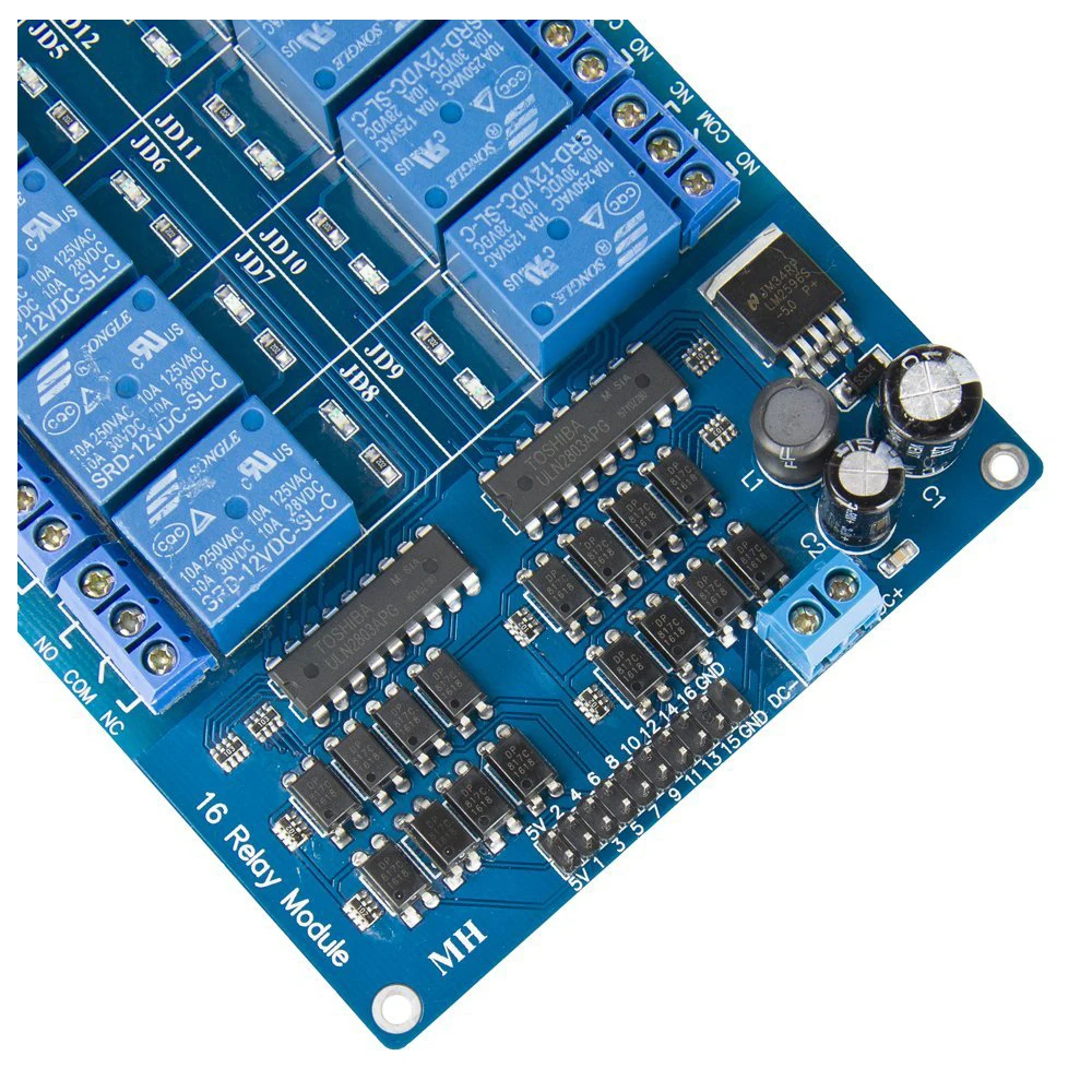
My planning was using these Arduino to driving my 16 Relays Module, but ruined.
So..

How I drive that Relay PCB with KL25Z? My planning is use Open Frame 2N 12v... Is ok? Too weak?
What "booster" or how many Amperes I'm need for 5v of this Relay Board?

Or is need buy a new Arduino or Drive/Shield? Possible to hack these to use MOSFETs? I've read the theoric possibility use of these PCB Relay in Solenoids because have Optocouplers...

Thanks in advance, sorry my english.


HTB1sEQJc8E_1uJjSZFOq6xNwXXaY.jpg


Edited by JeanDrEaD, 17 January 2018 - 12:16 AM.


#530 mjr

mjr

    Pinball Wizard

  • Members
  • PipPipPipPipPip
  • 3,331 posts

  • Flag: United States of America

  • Favorite Pinball: Medieval Madness

Posted 17 January 2018 - 04:11 AM

How I drive that Relay PCB with KL25Z?  What "booster" or how many Amperes I'm need for 5v of this Relay Board?


Some of those relay boards will work with the KL25Z, but most of them won't.  There are two problems that most of them have:


- The take too much current to trigger.  The KL25Z can only handle 4mA on a GPIO pin.  These relay boards usually have opto inputs that require about 20mA to trigger.


- They require 5V to trigger.   These relay boards are all designed for Arduinos, which are mostly 5V devices.  The KL25Z is a 3.3V device.


If you have any specs on the relay board, that might tell you if it's safe to use with the KL25Z, but unfortunately it probably isn't because of the 3.3V design and 4mA limit.


Possible to hack these to use MOSFETs?


You could, but if you're going to do that, I'd recommend forgetting about the relay board and ONLY using the MOSFETs.  A simple MOSFET circuit you can build yourself for about $3 per channel can handle any solenoid DIRECTLY, with no relay board involved.


There's a schematic for a MOSFET driver circuit in the Pinscape V1 Build Guide:


- Go to https://os.mbed.com/..._Controller_V2/


- Find "V1 Hardware Build Guide (PDF)"


- Click the link


- Search for "Build the LedWiz output drivers"


That will take you to the circuit diagram and how to wire it to the KL25Z and your solenoids.  It's a complete high-power output driver - you won't need any relays or anything else with it.


 My planning is use Open Frame 2N 12v... Is ok? Too weak?


Lots of people use solenoids like those, so there's some chance they'll work for you.  I personally think they're too weak to be truly realistic, but if you already have them you should test them out and see how you like them.


The most popular device for flippers, bumpers, and slingshots is the Siemens contactors.  They produce a somewhat heavier sounding thud that's a little closer to reality, but they're not quite all the way there either, and they can be quite expensive.


Another popular option is automotive starter solenoids.  I haven't tested any of those myself so I don't have a first-hand opinion on them, but they're cheaper than the Siemens contactors and are probably in the same ballpark in terms of effect.


#531 JeanDrEaD

JeanDrEaD

    Hobbyist

  • Members
  • PipPip
  • 12 posts

  • Flag: Brazil

  • Favorite Pinball: Attack from mars, Monster of black lagoon

Posted 17 January 2018 - 11:50 AM


Some of those relay boards will work with the KL25Z, but most of them won't.  There are two problems that most of them have:


- The take too much current to trigger.  The KL25Z can only handle 4mA on a GPIO pin.  These relay boards usually have opto inputs that require about 20mA to trigger.


- They require 5V to trigger.   These relay boards are all designed for Arduinos, which are mostly 5V devices.  The KL25Z is a 3.3V device.


If you have any specs on the relay board, that might tell you if it's safe to use with the KL25Z, but unfortunately it probably isn't because of the 3.3V design and 4mA limit.


Yeah, I've make 2 mistakes, bought the wrong arduino and don't pay attetion to relay board input... Noobism haha
So are impossible to me boost that GPIO 4mA to high? :(


Lots of people use solenoids like those, so there's some chance they'll work for you.  I personally think they're too weak to be truly realistic, but if you already have them you should test them out and see how you like them.


The most popular device for flippers, bumpers, and slingshots is the Siemens contactors.  They produce a somewhat heavier sounding thud that's a little closer to reality, but they're not quite all the way there either, and they can be quite expensive.


Another popular option is automotive starter solenoids.  I haven't tested any of those myself so I don't have a first-hand opinion on them, but they're cheaper than the Siemens contactors and are probably in the same ballpark in terms of effect.

I'm thinkg in those because low costs and because my playfield are only HD 768p 32" LCD... Most cheapest possible... I only need Fun, impossible spend(brazil = u$ x4 + Tax) in "real" simulation by now...

Thanks again!


Edited by JeanDrEaD, 17 January 2018 - 11:51 AM.


#532 mjr

mjr

    Pinball Wizard

  • Members
  • PipPipPipPipPip
  • 3,331 posts

  • Flag: United States of America

  • Favorite Pinball: Medieval Madness

Posted 17 January 2018 - 06:56 PM

So are impossible to me boost that GPIO 4mA to high? :(


Not impossible, you just need some kind of external circuitry along the lines of the MOSFET circuit in the V1 Build Guide.  And I figure if you're going to go to the trouble of building an external booster circuit, you might as well use only the booster circuit, since it can do the whole job itself, without any relays involved at all.  And the MOSFET setup is better than the relays since it can do PWM, which the relays can't.


Edited by mjr, 17 January 2018 - 06:57 PM.


#533 JeanDrEaD

JeanDrEaD

    Hobbyist

  • Members
  • PipPip
  • 12 posts

  • Flag: Brazil

  • Favorite Pinball: Attack from mars, Monster of black lagoon

Posted 17 January 2018 - 10:45 PM


So are impossible to me boost that GPIO 4mA to high? :(


Not impossible, you just need some kind of external circuitry along the lines of the MOSFET circuit in the V1 Build Guide.  And I figure if you're going to go to the trouble of building an external booster circuit, you might as well use only the booster circuit, since it can do the whole job itself, without any relays involved at all.  And the MOSFET setup is better than the relays since it can do PWM, which the relays can't.


So I will buy 16 BUK9575 55A(or 100A, found it with half price in aliexpress) and exchange the Relays in PCB to MOSFETs...
The PCB of Relay have two ULN2803A, sixteen PC817 and one LM2956, I guess I can do this hack...

I'll report any progress(the itens are oversea coming to jungle)...

Thanks again mjr!


#534 Onevox

Onevox

    VP Zealot

  • Members
  • PipPipPip
  • 269 posts
  • Location:Virginia, USA

  • Flag: United States of America

  • Favorite Pinball: The Getaway, High Speed II

Posted 18 January 2018 - 01:32 AM

DOF light strips from main board RGB ports with little cheap 12v LED amplifiers worked great. After rigging night mode button, this was the final pinscape driven add on.


EDIT for posterity: With the 60 RGB LEDs, I had one 12V amp in the bottom cab for about 9 ft of LED strip. The amp lit well, but melted down on me, so I've replaced with two amps, and inserted one halfway in the line, so each has about 4.5 ft. of LEDs, ... daisy chained the 12V line to the second amp. So far so good. 

86906956b3b08a0cff6d07fa240e4c95.jpg


Sent from my iPhone using Tapatalk


Edited by Onevox, 05 February 2018 - 05:07 PM.

_____________________


My build: The Joker Poker.

http://www.vpforums....showtopic=37574


#535 STV

STV

    Enthusiast

  • Members
  • PipPipPip
  • 436 posts

  • Flag: United States of America

  • Favorite Pinball: Varies. 140 in the list ATM.

Posted 18 January 2018 - 02:46 AM

Another popular option is automotive starter solenoids.  I haven't tested any of those myself so I don't have a first-hand opinion on them, but they're cheaper than the Siemens contactors and are probably in the same ballpark in terms of effect.


I have both.  The solenoids (3) are mounted near the back for bumpers.  The contactors are in the front (4) for slings and flippers.   Hard to explain the big difference.  Contactors are a much warmer, smoother softer thunk feel as opposed to the solenoids louder harder clack.  I'm already replacing the solenoids however.. after about a year they started failing.  


#536 DesertStorm

DesertStorm

    Hobbyist

  • Members
  • PipPip
  • 17 posts

  • Flag: ---------

  • Favorite Pinball: White Water

Posted 27 January 2018 - 12:49 PM

Hello, i have some questions about the pinscape and the expansion boards i have. (Sorry for my level of english, im spanish)


1. I understand the high power outs only gives the negatives, and I need to attach my outputs with a suply and diode. But my question is, "JP11 Medium Power Outputs" of the main board is the same working? Or provides positive and negative? Id like to connect the lights of the buttons direct in this outputs, if its possible. If not, I need to use the high power board? Im little confused about the button lights, I hope you can clarify a little.


2.  Can I power the "pc psu" and the "2nd psu" of the expansion boards with only one external psu? is because i dont have the pc inside my cabinet, is about 8m. far. Id like to use only one apart psu that I put inside the cabinet instead having to pass wires from the pc to the pinball.


Thankyou.


PD: I have to edit the post because always I post something appears in blank


Edited by DesertStorm, 27 January 2018 - 12:52 PM.


#537 mjr

mjr

    Pinball Wizard

  • Members
  • PipPipPipPipPip
  • 3,331 posts

  • Flag: United States of America

  • Favorite Pinball: Medieval Madness

Posted 27 January 2018 - 08:12 PM

1. I understand the high power outs only gives the negatives, and I need to attach my outputs with a suply and diode. But my question is, "JP11 Medium Power Outputs" of the main board is the same working? Or provides positive and negative? Id like to connect the lights of the buttons direct in this outputs, if its possible.


Yes, it works the same way as the others, and button lights will work fine there.  The flasher outputs have more limited power (1.5A max) than the power board outputs (4A max), but 1.5A is plenty for the button lights.  The #555 bulbs run at about 250mA.


All outputs on all of the boards work the same way - they all get connected to the negative side, and you connect the (+) side directly from the device to the power supply.


JP11 has a +5V power supply pin intended as a convenience for wiring a standard set of flashers, but it's only there for convenience.  You can just leave it disconnected if you need a different voltage.


More details on feedback wiring in general:  http://mjrnet.org/pi...=feedbackWiring

And on the Pinscape boards in particular:  http://mjrnet.org/pi...p?sid=psOutputs


2.  Can I power the "pc psu" and the "2nd psu" of the expansion boards with only one external psu? is because i dont have the pc inside my cabinet, is about 8m. far. Id like to use only one apart psu that I put inside the cabinet instead having to pass wires from the pc to the pinball.


Yes, you can connect both power connectors (PC PSU and 2ND PSU) to the same power supply. 


Usually people ask about doing it the opposite way - connecting both power inputs to the main PC power supply and not bothering with a second PSU.  That's technically okay too, but I always recommend using a second PSU for feedback devices.  In your case, you do have the second toy-only PSU, so you're good as far as that goes.  The only downside to connecting both power inputs to the secondary power supply is that it reduces the amount of isolation between the logic circuits and power circuits.  More isolation is better because the power circuit side can be quite "noisy" (electrically speaking) with all of the mechanical devices in play.  But the amount of isolation you get even with the recommended setup with two ATX power supplies is modest, so I think you'll be okay.


Edited by mjr, 27 January 2018 - 08:15 PM.


#538 DesertStorm

DesertStorm

    Hobbyist

  • Members
  • PipPip
  • 17 posts

  • Flag: ---------

  • Favorite Pinball: White Water

Posted 28 January 2018 - 07:23 PM


1. I understand the high power outs only gives the negatives, and I need to attach my outputs with a suply and diode. But my question is, "JP11 Medium Power Outputs" of the main board is the same working? Or provides positive and negative? Id like to connect the lights of the buttons direct in this outputs, if its possible.


Yes, it works the same way as the others, and button lights will work fine there.  The flasher outputs have more limited power (1.5A max) than the power board outputs (4A max), but 1.5A is plenty for the button lights.  The #555 bulbs run at about 250mA.


All outputs on all of the boards work the same way - they all get connected to the negative side, and you connect the (+) side directly from the device to the power supply.


JP11 has a +5V power supply pin intended as a convenience for wiring a standard set of flashers, but it's only there for convenience.  You can just leave it disconnected if you need a different voltage.


More details on feedback wiring in general:  http://mjrnet.org/pi...=feedbackWiring

And on the Pinscape boards in particular:  http://mjrnet.org/pi...p?sid=psOutputs


2.  Can I power the "pc psu" and the "2nd psu" of the expansion boards with only one external psu? is because i dont have the pc inside my cabinet, is about 8m. far. Id like to use only one apart psu that I put inside the cabinet instead having to pass wires from the pc to the pinball.


Yes, you can connect both power connectors (PC PSU and 2ND PSU) to the same power supply. 


Usually people ask about doing it the opposite way - connecting both power inputs to the main PC power supply and not bothering with a second PSU.  That's technically okay too, but I always recommend using a second PSU for feedback devices.  In your case, you do have the second toy-only PSU, so you're good as far as that goes.  The only downside to connecting both power inputs to the secondary power supply is that it reduces the amount of isolation between the logic circuits and power circuits.  More isolation is better because the power circuit side can be quite "noisy" (electrically speaking) with all of the mechanical devices in play.  But the amount of isolation you get even with the recommended setup with two ATX power supplies is modest, so I think you'll be okay.


Thankyou very much for the information is very usefull.


#539 DesertStorm

DesertStorm

    Hobbyist

  • Members
  • PipPip
  • 17 posts

  • Flag: ---------

  • Favorite Pinball: White Water

Posted 02 February 2018 - 11:02 PM

I have one strange problem, In the main board I can connect inputs and outputs (button leds and 555 bulbs) and all works fine, including DOF, etc. This is OK but:


The expansion power board doesn't seems to work. I tried to put one 12V DC motor (with the diode) and when I use the output test of the pinscape config software, the motor don't move. But if I bring my hand near the expansion board, the motor starts to work, in all the outputs. (that is, if I touch any part of the board, specially over the pics). 


My scheme is:   one external PSU breading all pinscape boards (pcpsu and 2nd psu), and providing 12V to a motor, the motor has a diode (negative part in the positive of the motor and vice versa) and the negative of the motor in the expansion board.


Sin_t_tulo.jpg


Any idea that what can cause this? There is any soft to test the correct work of the boards that detect if any go wrong automatically? Mjr you know my problem with the diode on main board, can be any sequel?


#540 mjr

mjr

    Pinball Wizard

  • Members
  • PipPipPipPipPip
  • 3,331 posts

  • Flag: United States of America

  • Favorite Pinball: Medieval Madness

Posted 03 February 2018 - 12:21 AM

DesertStorm - it looks like you've got everything wired correctly...


> But if I bring my hand near the expansion board, the motor starts to work,

> in all the outputs.


Hmm, that suggests to me that you have a bad connection somewhere. What you're probably doing by moving your hand around is placing a static charge on a disconnected logic pin, which is raising or lowering the charge on the pin enough to flip a logic level from 0 to 1 or vice versa, or maybe charge one of the MOSFET gates.  That *shouldn't* happen, because everything that could be affected like that should already be connected internally to a nice solid logic 0 or 1 voltage level all the time, and that should always readily overwhelm the effect of any static charge from placing your hand near the board.  So the fact that is happening suggests that there's a loose or broken connection somewhere, so that a logic pin is "floating" without a solid connection to any reference voltage.  Given that it affects all the ports, I'd guess it's one of the main data connections going into the TLC5940s, or maybe one of the power connections. 


The first thing to check is probably the ribbon cable connecting the two boards.  Make sure it's seated firmly on both ends, and check that the ribbon cable plugs are well seated on the cable.  You might try getting out a pair of pliers and squeezing the connectors on the end of the cable a little bit (with the cable unplugged) just in case one of the IDC pins didn't quite pierce the insulation properly when it was originally assembled.  If that doesn't make any difference, I'd get out a magnifying glass and go over the bottom of the power board to see if I could spot any bad solder joints - places where it looks like there's a gap between the solder and the leg of an IC pin, for example.


Edited by mjr, 03 February 2018 - 12:23 AM.