Jump to content


Photo
* * * * * 7 votes

Pinscape expansion board support thread


  • Please log in to reply
1103 replies to this topic

#481 mjr

mjr

    Pinball Wizard

  • Members
  • PipPipPipPipPip
  • 3,331 posts

  • Flag: United States of America

  • Favorite Pinball: Medieval Madness

Posted 01 December 2017 - 05:57 AM

Last question. Can the primary and secondary 5v come from the same 2nd power supply.


The "PC PSU" really has to be connected to the motherboard/PC PSU.  That's important because that part of the circuit is all connected to the PC motherboard via the USB wiring.  You shouldn't use a separate power supply for that input because there could be voltage level differences that could be harmful to your motherboard.


#482 yagesz

yagesz

    Enthusiast

  • Platinum Supporter
  • 303 posts
  • Location:Wyoming

  • Flag: United States of America

  • Favorite Pinball: TAF, TSPP, Metallica, CV

Posted 01 December 2017 - 06:04 AM

Copy that. Ordering a f ton of new parts


Sent from my iPhone using Tapatalk

#483 Fusionwerks

Fusionwerks

    Poorly recovering pinball addict

  • Platinum Supporter
  • 417 posts

  • Flag: United States of America

  • Favorite Pinball: JP (DE), Deadpool, James Bond 007

Posted 01 December 2017 - 06:09 AM

Like Mike said, they should be separate to isolate the logic and power circuitry, but they don't have to be.


I did the same thing you did, and bought separate voltage power supplies thinking that i could isolate troubleshooting in the future. I hope you didn't use my build list as a reference for what you have to use. I HAD a 12v power supply and it fried in the first week after i got everything done. I think the shaker motor did it. I was lucky and had an extra 650w PSU power supply and had it back up and running in a few minutes.


I've never used or seen Zebs light bar, but is it possible to de-solder and replace the resistors to a different value?


Especially since everybody that has a Pinscape board is a soldering expert now right?  ;)


#484 yagesz

yagesz

    Enthusiast

  • Platinum Supporter
  • 303 posts
  • Location:Wyoming

  • Flag: United States of America

  • Favorite Pinball: TAF, TSPP, Metallica, CV

Posted 01 December 2017 - 03:17 PM

Like Mike said, they should be separate to isolate the logic and power circuitry, but they don't have to be.
 
I did the same thing you did, and bought separate voltage power supplies thinking that i could isolate troubleshooting in the future. I hope you didn't use my build list as a reference for what you have to use. I HAD a 12v power supply and it fried in the first week after i got everything done. I think the shaker motor did it. I was lucky and had an extra 650w PSU power supply and had it back up and running in a few minutes.
 
I've never used or seen Zebs light bar, but is it possible to de-solder and replace the resistors to a different value?
 
Especially since everybody that has a Pinscape board is a soldering expert now right?  ;)


I always planned separate psu and didn’t check stuff. Oh well. I ordered a ATX breakout board as well as a 16pin idt breakout board so I can wire everything without tearing it apart. The resistors are almost flush with his board so nope won’t try. And I hate soldering small things. I got lucky and found someone stateside that hooked me up with a Pin2Dmd and completes pinscape for pretty cheap. And I have a 650w psu entourage from Newegg. Also ordered 30cm Arduino breakout cables so I don’t have to crimp a ton of DuPont connectors and can just hook up to terminal strips. Should be easy now.


Sent from my iPhone using Tapatalk

#485 Fusionwerks

Fusionwerks

    Poorly recovering pinball addict

  • Platinum Supporter
  • 417 posts

  • Flag: United States of America

  • Favorite Pinball: JP (DE), Deadpool, James Bond 007

Posted 01 December 2017 - 06:57 PM

those DuPont connectors are a bitch. Even with the correct crimpers. I ended up buying breakout cables too and spliced them to the device wires, but i removed the connector from the plastic and snapped it into the connectors MJR recommended.


Are you taking pictures of your build?


#486 yagesz

yagesz

    Enthusiast

  • Platinum Supporter
  • 303 posts
  • Location:Wyoming

  • Flag: United States of America

  • Favorite Pinball: TAF, TSPP, Metallica, CV

Posted 01 December 2017 - 09:36 PM

those DuPont connectors are a bitch. Even with the correct crimpers. I ended up buying breakout cables too and spliced them to the device wires, but i removed the connector from the plastic and snapped it into the connectors MJR recommended.


Are you taking pictures of your build?


My build was done until somebody early xmas me the money to do DOF. Just need a couple small things afterwards (Blower, Beacons) I have a chime set and Bell from an EM I just sold


#487 adrinef

adrinef

    Neophyte

  • Members
  • Pip
  • 5 posts

  • Flag: United States of America

  • Favorite Pinball: The Twilight Zone

Posted 04 December 2017 - 06:32 PM

I'm not currently using the KL25Z with the expansion boards(I do have a blank set and will build in the future) so if this isn't a suitable place to ask the question please delete or move it. 


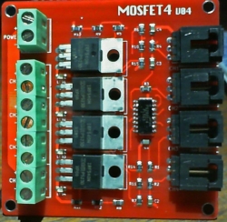
I have the KL25Z connected to a premade 4 channel mosfet board to drive my contactors.  On the left side I have the 24v power and ground coming in. The right side needs 5v and ground. Does the 5v have to come from the KL25Z J9-10 or can it be supplied by a secondary power supply?

I currently have it connected to a secondary power supply and it is working but would like to know if there is a potential for frying something having it setup this way.


Thanks!


#488 mjr

mjr

    Pinball Wizard

  • Members
  • PipPipPipPipPip
  • 3,331 posts

  • Flag: United States of America

  • Favorite Pinball: Medieval Madness

Posted 04 December 2017 - 06:55 PM

I'm not currently using the KL25Z with the expansion boards(I do have a blank set and will build in the future) so if this isn't a suitable place to ask the question please delete or move it. 


I have the KL25Z connected to a premade 4 channel mosfet board to drive my contactors.  On the left side I have the 24v power and ground coming in. The right side needs 5v and ground. Does the 5v have to come from the KL25Z J9-10 or can it be supplied by a secondary power supply?

I currently have it connected to a secondary power supply and it is working but would like to know if there is a potential for frying something having it setup this way.


I can't say for sure without knowing how your MOSFET boards are wired internally, but assuming they follow the standard design for these sorts of things, I think you should be fine getting the +5V input from a secondary power supply.  


#489 adrinef

adrinef

    Neophyte

  • Members
  • Pip
  • 5 posts

  • Flag: United States of America

  • Favorite Pinball: The Twilight Zone

Posted 04 December 2017 - 07:54 PM

This is the pic of the MOSFET board. I've been unable to find a schematic of this particular one. It does appear to be used often in builds that I've seen.  On the left side the power connections are all connected on each channel. On the right side the 5v and grounds are connected on each channel.  I realize that doesn't help much, just thought I would throw it out there in case you or someone else is familiar with it. 


detail_60_MOSFET4V4.jpg


#490 mjr

mjr

    Pinball Wizard

  • Members
  • PipPipPipPipPip
  • 3,331 posts

  • Flag: United States of America

  • Favorite Pinball: Medieval Madness

Posted 04 December 2017 - 08:29 PM

That looks like it's probably this one: http://yourduino.com...uct_detail&p=60


Schematic from their site, in case the link breaks in the future:


 mosfet4v04.jpg


If I'm reading it correctly, your +5V input isn't actually connected internally, so it really doesn't matter at all where you supply it from!  If I'm right, you should be able to unplug the 5V entirely and everything should still work.


What are you connecting to the big green "Power" input connectors on the left side?  If that's connected to 24V, you probably should change it to 5V or 12V.  That looks like the connection that's driving the MOSFET gate, and the Vgs(max) for that part is 20V, so I think you're pushing your luck with 24V.   From the MOSFET data sheet it looks like 5V is sufficient and 12V is completely safe.  You can definitely supply either of those from the secondary power supply safely.


The 24V is still fine for the actual feedback device power, though.  But you should only connect the +24V directly to the feedback device, not to anything on the MOSFET board.


Edited by mjr, 04 December 2017 - 08:32 PM.


#491 adrinef

adrinef

    Neophyte

  • Members
  • Pip
  • 5 posts

  • Flag: United States of America

  • Favorite Pinball: The Twilight Zone

Posted 04 December 2017 - 10:42 PM

I believe that schematic is for their previous version of the board that used a 4n35m optocoupler for each channel.  This board has an IC with PS2801-4 stamped  on it, which I guess is closer to the sample circuit from your V1 build guide. 


Yes, I currently have the 24v on the big green power input on the left side.  I believe my thinking was that you connect the supply that you want switched here, not what is needed to turn it on the MOSFET.
I believe I went off of this schematic, not sure which forum it was from. 


I don't have anything connected to the +side of each channel. I have 24V going to the contactor, and the ground of each channel connecting to the negative on the contactor.


#492 mjr

mjr

    Pinball Wizard

  • Members
  • PipPipPipPipPip
  • 3,331 posts

  • Flag: United States of America

  • Favorite Pinball: Medieval Madness

Posted 04 December 2017 - 11:17 PM

I believe that schematic is for their previous version of the board that used a 4n35m optocoupler for each channel.  This board has an IC with PS2801-4 stamped  on it


I'm sure you're right.  My guess is it's essentially the same circuit with the different part substituted - most of those optos are pretty similar.


Yes, I currently have the 24v on the big green power input on the left side.  I believe my thinking was that you connect the supply that you want switched here, not what is needed to turn it on the MOSFET.


These sorts of circuits don't actually switch the "+" power.  They only switch the "-" side.  The "+" power going into the board is for a control function - to drive the MOSFET gate in this case. 


You're probably not in imminent danger of melting the MOSFETs with 24V, but I suspect you're stressing them.  I'd try lowering that input to 12V and verify that it still works; if so, it'll be better for the longevity of the board.


I don't have anything connected to the +side of each channel. I have 24V going to the contactor, and the ground of each channel connecting to the negative on the contactor.


Yep, that seems right.


#493 adrinef

adrinef

    Neophyte

  • Members
  • Pip
  • 5 posts

  • Flag: United States of America

  • Favorite Pinball: The Twilight Zone

Posted 05 December 2017 - 05:44 AM

mjr,


You are correct about the circuit not needing the +5v.

I also replaced the 24v with 12v and everything appears to be working the same.

Thanks for the help and all the hard work on the Pinscape Project!


#494 BorgDog

BorgDog

    We come in peace.. shoot to kill.. shoot to kill.

  • Members
  • PipPipPipPip
  • 1,427 posts
  • Location:Leavenworth, WA

  • Flag: United States of America

  • Favorite Pinball: Alien Star, TNA


Posted 06 December 2017 - 11:19 PM

Hi Mike,
 
I'm finally about ready to start building my expansion boards, just need to send in a big mouser order.  Just had a couple questions (sorry haven't read every page of this thread).
 
Is it possible to do the setup without the Power Board?  Just the Main Board and 2 Chime boards?  Most of the toys in my cab are actual pinball mechs on 24V (2 flippers, 3 pops, 2 slings, 3 chimes, a bell and a knocker), plus I have 3 12v starter solenoids.  Doing the math I need to build 2 chime boards for the real mechs, and the only things I would have on the Power board would be the flippers and maybe the starter solenoids if I wanted to pwm them.  no lights, no shaker, etc. 
 
If it is possible to do that, could I bypass the timer on 2 of the chime board outputs so I can hook the flippers to them and not have them shut off while I'm holding them down.
 
Thanks for all your work and support,
 
Dan


#495 mjr

mjr

    Pinball Wizard

  • Members
  • PipPipPipPipPip
  • 3,331 posts

  • Flag: United States of America

  • Favorite Pinball: Medieval Madness

Posted 07 December 2017 - 12:28 AM

Is it possible to do the setup without the Power Board?  Just the Main Board and 2 Chime boards?  


Absolutely - it's all mix-and-match. :)


Most of the toys in my cab are actual pinball mechs on 24V (2 flippers, 3 pops, 2 slings, 3 chimes, a bell and a knocker), plus I have 3 12v starter solenoids.  Doing the math I need to build 2 chime boards for the real mechs, and the only things I would have on the Power board would be the flippers and maybe the starter solenoids if I wanted to pwm them.  no lights, no shaker, etc. 


That does sound perfect for the chime boards.


If you ever did want to add flashers and a strobe, you have the outputs on the main board for that.


And if you change your mind later and end up adding a bunch of stuff requiring PWM, you can simply add a power board to your system at that point.  You can add or remove boards from the system at any time - it's just a matter of plugging in the boards you want and updating the settings in the Config Tool to tell it what's currently attached.


If it is possible to do that, could I bypass the timer on 2 of the chime board outputs so I can hook the flippers to them and not have them shut off while I'm holding them down.


Yes, and in fact, the chime boards have a timer bypass option designed in for just this kind of situation. 


To do that, pick out the output you want to control directly with no timer.  Once you have one picked out...


Step one:  Find the block on the board for that output - there's a white rectangle drawn around the whole block for each timer circuit on the silkscreen.  


Step two:  You're going to OMIT all of the parts in that block, EXCEPT the PC817 opto chip.  (So it's actually easier to build if you want to bypass a timer!)


Step three:  But now you're going to add in two parts that aren't normally there.


3A:  The first part to add is a simple wire connector in place of the resistor marked "BYPASSn".  It's marked on the board as a resistor, but it's actually a "0 Ohm" resistor, which is equivalent to just soldering a piece of wire across the terminals.


3B:  The second part to add is a 270 Ohm resistor.  If you look closely, you'll see a white diagonal line drawn across two of the side-by-side resistors, from one terminal on one to the opposite terminal on the other.  Install the 270 Ohm resistor into the holes connected by that diagonal line.


I hope that makes sense!  It mostly simplifies things to omit a timer because you can leave out about a dozen parts, but you do have to find those two special extras.  Hopefully it'll make sense when you look at the board.


When you're ordering parts, be sure to leave out the timer parts you won't need and add one 270 Ohm resistor for each bypassed timer.


Edited by mjr, 07 December 2017 - 12:30 AM.


#496 BorgDog

BorgDog

    We come in peace.. shoot to kill.. shoot to kill.

  • Members
  • PipPipPipPip
  • 1,427 posts
  • Location:Leavenworth, WA

  • Flag: United States of America

  • Favorite Pinball: Alien Star, TNA


Posted 07 December 2017 - 01:26 AM

awesome, Thanks Mike!


#497 adrinef

adrinef

    Neophyte

  • Members
  • Pip
  • 5 posts

  • Flag: United States of America

  • Favorite Pinball: The Twilight Zone

Posted 09 December 2017 - 07:51 AM

It's me again.


To refresh. I'm running KL25Z standalone with multiple 4 channel mosfet boards.
I have a Red led connected to the first PWM output PTA1

I have PTA2 wired to the mosfet board but nothing is connected to the other side.

I have a blue led strip connected to the third PWM output PTD4.


In the DOF Config I have port 1 set at RGB Undercab Complex. Port 2 would be green, and 3 blue.


I have 8 contactors starting at output 11-18.


I have DirectOutput setup and updated with the version from your website.


I have DOFLinx setup for FX2 and Future Pinball.


I'm using PinballX as a frontend, not currently using Feedback in it.  In testing I've found that often when I exit Visual Pinball, FX2, or Future Pinball and return to PinballX whichever of the PWM outputs that were on will stay on.  If i go back into another table, leds and contactors  works as they should. If I exit PinballX they continue to stay on.  If I run the Pinscape Config tool and click test outputs, and move the slider on any one of the PWM outputs it will reset all 3(if they were all stuck on) and turn that particular one on or off.


I switched out the Mosfet board with another and it behaves the same way. Once while all 3 were stuck on I checked the voltage on the 3 outputs, 1 was around 3.0 volts, the other 2 were between 0-1 volts.


I'm not sure if this is normal, a software problem(not releases resources when exiting), or a wiring problem.


Is it normal for the PWM ports to flash momentarily when connecting the usb cable to the KL25Z or when the computer is booting and starts applying power on the usb?


None of the contactors fire when plugging the usb cable, while booting or get stuck on when exiting a table.


Thanks!


#498 mjr

mjr

    Pinball Wizard

  • Members
  • PipPipPipPipPip
  • 3,331 posts

  • Flag: United States of America

  • Favorite Pinball: Medieval Madness

Posted 09 December 2017 - 07:09 PM

I'm using PinballX as a frontend, not currently using Feedback in it.  In testing I've found that often when I exit Visual Pinball, FX2, or Future Pinball and return to PinballX whichever of the PWM outputs that were on will stay on.  If i go back into another table, leds and contactors  works as they should. If I exit PinballX they continue to stay on.  If I run the Pinscape Config tool and click test outputs, and move the slider on any one of the PWM outputs it will reset all 3(if they were all stuck on) and turn that particular one on or off.


I switched out the Mosfet board with another and it behaves the same way. Once while all 3 were stuck on I checked the voltage on the 3 outputs, 1 was around 3.0 volts, the other 2 were between 0-1 volts.


I'm not sure if this is normal, a software problem(not releases resources when exiting), or a wiring problem.


Given that this happens during the program transition points, it sounds like it's about 99% certain to be a software issue, and your test with swapping the boards certainly strengthens that case.  I think you're right that it's simply a matter of VP/FP failing to turn everything off before they exit.  The KL25Z obviously has no way of knowing what program is running on the PC - it can only respond to ON/OFF commands from the PC.  If VP sends an ON command and then exits without cleaning up, the KL25Z has no way of knowing that VP is gone, so that port is going to stay on forever (or until another program starts up and sends an OFF command).


However, I wouldn't say this is normal.  It doesn't happen on my cab, for example.  DOF is good about explicitly turning off all ports when the host program exits.  So I'd guess that what's happening is that VP isn't exiting normally for some reason - the VP process must be getting terminated abruptly so that DOF doesn't get a chance to clean up on the way out.  I don't know why that would be happening, but that seems like the most likely cause.


I'm not sure about FP, though - it doesn't use DOF, so it doesn't get the benefit of DOF's termination cleanup.  I think it's up to the individual table scripts in FP to clean up properly at exit.


Is it normal for the PWM ports to flash momentarily when connecting the usb cable to the KL25Z or when the computer is booting and starts applying power on the usb?


None of the contactors fire when plugging the usb cable, while booting or get stuck on when exiting a table.


The flashing is more or less normal.   When the KL25Z first comes out of a power cycle or reboot, all of the GPIO ports are in a sort of disconnected internal state ("high impendance").  One of the first things the software does is configure the ports.  That configuration step connects them electrically inside the KL25Z, and that causes a brief electrical transient on the output.  The flash is being caused by that little switching glitch.  The contactors are actually getting pulsed too, but the pulse is so brief that it doesn't usually translate into any noticeable effect on mechanical devices like contactors or solenoids.  If you were using incandescent bulbs instead of LEDs, you probably wouldn't see it either, as the flash would be so dim.  LEDs are just so efficient that they make the glitch visible. 


If you were using the expansion boards, you'd likely see the same thing for different (but related) reasons.  The TLC5940 PWM controller chips on the expansion boards power up in a randomized state, so their outputs are all at some random brightness level for the millisecond or so that it takes the software to start up and send them OFF commands.


#499 mrjoin3r

mrjoin3r

    Neophyte

  • Members
  • Pip
  • 9 posts

  • Flag: United Kingdom

  • Favorite Pinball: the simpsons

Posted 10 December 2017 - 05:58 PM

Well took the plunge and ordered the expansion board and powerboard from Elcrow, just waiting for them to be delivered. I've just checked the mouser parts list for the expansion board and two of the parts, the (Multilayer Ceramic Capacitors MLCC - Leaded 4.7uF 10volts X5R +/-10%) and the (Transistor Output Optocouplers Optocplr Phototrans 4-CHNL) are on back order in the UK until February, March 2018 :(. Could anyone suggest alternatives for these and where I might get them from? I'm a complete beginner when it comes to electronics so will be asking many questions as I try and work through this, hope everyone can put up with the many questions I will inevitably be asking.

#500 mjr

mjr

    Pinball Wizard

  • Members
  • PipPipPipPipPip
  • 3,331 posts

  • Flag: United States of America

  • Favorite Pinball: Medieval Madness

Posted 10 December 2017 - 10:00 PM

Well took the plunge and ordered the expansion board and powerboard from Elcrow, just waiting for them to be delivered. I've just checked the mouser parts list for the expansion board and two of the parts, the (Multilayer Ceramic Capacitors MLCC - Leaded 4.7uF 10volts X5R +/-10%) and the (Transistor Output Optocouplers Optocplr Phototrans 4-CHNL) are on back order in the UK until February, March 2018 :(. Could anyone suggest alternatives for these and where I might get them from? I'm a complete beginner when it comes to electronics so will be asking many questions as I try and work through this, hope everyone can put up with the many questions I will inevitably be asking.


For things like capacitors and resistors, you can substitute pretty much any part with the same specs.  In the case of a cap, the important spec is the 4.7uF.  The voltage rating for a capacitor is always a minimum, so you can substitute anything with the stated rating (10V in this case) or higher.  For a 10V, that's pretty much anything, since you'd be hard pressed to find one rated lower.  4.7uF is a very common size, so a Mouser search should turn up lots of alternatives - the only problem is that it'll turn up so many alternatives that it's a pain to pick one, but for this sort of thing I usually just sort on price and pick a cheap one that matches the specs I need.


The only other thing to pay attention to is physical form factor.  Check out the little thumbnail image on Mouser and make sure it looks roughly the same as the original part.  You can look more closely at the size specs in the data sheet if you're not sure.  Caps come in a couple of basic shapes, so if the spec is the same and the basic shape in the thumbnail is similar, it'll probably fit.


The optocouplers are interchangeable with anything with an xx847 label.  There are several equivalent versions with different letters in the first two places.  The letters amount to manufacturer IDs for otherwise equivalent generic parts.  And in the off chance that you can't find any xx847 anywhere, you can substitute FOUR xx817 parts for each xx847.  The xx817 is the single-gang version of the xx847, and it happens to be just about exactly 1/4 of the package size, so four of the 817 parts will fit into the space meant for the 847 pretty easily.  I'd still try to find an 847, though, since it's a more perfect fit, plus it's a little easier to install one chip than four (and a little less error-prone orienting them, with fewer chips to worry about).


There's a list of other electronics vendors in the "Resources" chapter in the v2 build guide:

http://mjrnet.org/pi...p?sid=resources


They're all in the US as well, though, so that's probably not too helpful if you're looking for UK/EU alternatives to Mouser.  I'm sure there are some good options closer to home, but I'll have to leave it to your googling skills to find them, unless someone else has a suggestion or two.


Edited by mjr, 10 December 2017 - 10:07 PM.