


Sorry for the late answer. Did not subscribe to thread properly. Done that now.
Yeah, the fun of developing my own solution is something I'm going to miss. But since this is a field of expertise that I am not too experienced with it would be a daunting task. I've made a few Arduino and MicroChip standalone solutions. But this is a step up in complexity. Maybe I can help with some contributions to the project in the future. No promises.
About the vinyl cutting approach. What I get from the cutter is very, very accurate. It is then transferred with transfer tape to the metal foil (or acrylic). If I can get the transfer with those tiny bars down without any of them coming loose then is should be "perfect". So there is no hand cutting here, It is done by machine with CNC like accuracy. It might fail due to the bars being too narrow for the cutter to handle or the transfer process becoming too hard. I'll make some tests. If it works the contrast of this solution would be better than having a transparent film on top I think.
Another alternative for acrylic I think is to use a circuit board (PCB). Polish up the copper, Apply the bars and spray with clear paint so it will not corrode, and protect the bars from coming loose. Just a thought. In fact there is thin flexible copper film available that can be used as a a flexible PCB in clothes. Might work as a base for the bars as well. Easy to cut. Acrylic mirror might be the best, but I am not sure how I will have it cut. Never heard of anyone having a laser cutter nearby... A dremel is probably the best I can come up with.
But if smoothness is the thing for the friction problem then I guess it is best to find a plastic or metal guide that is of proper dimensions, use it as-is and glue the scale part on top.
What is the state of this sensor project as of now? THE solution, or is the glide pot sensor the way to go?


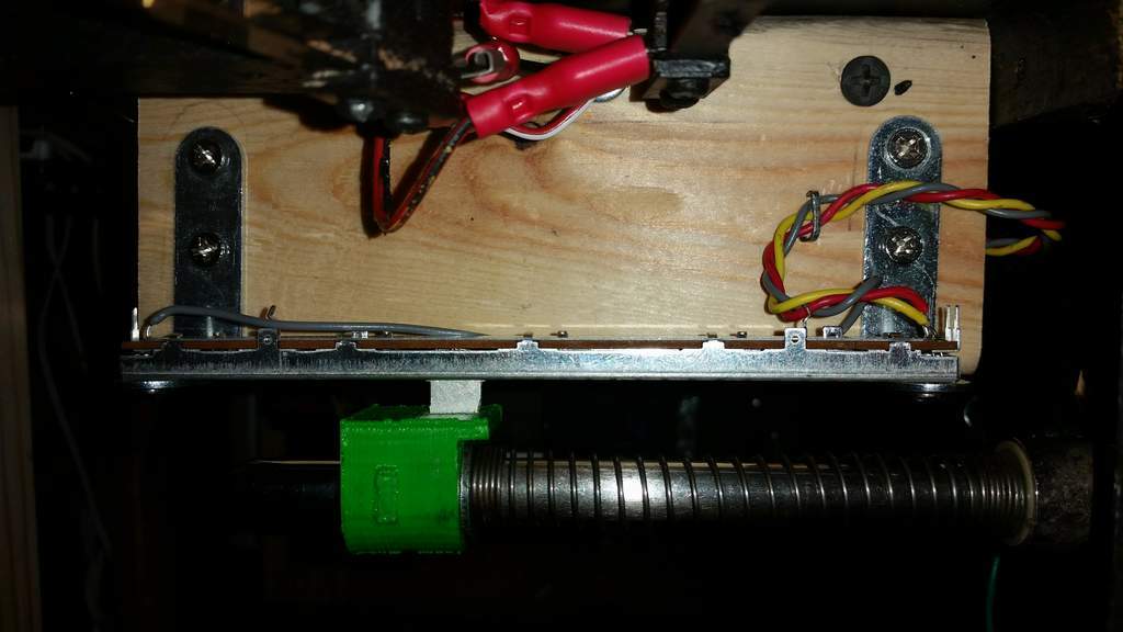
 But yes, it's "alive" in that I think it's the best sensor option available at the moment. It works great; the main downside is the degree of difficulty. The second best option is the slide potentiometer.


 )
) :
:


 are all trademarks of VPFORUMS.
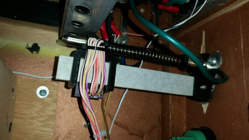