Jump to content


Photo

90's Workshop: Buildin' The Table


  • Please log in to reply
369 replies to this topic

#261 wtiger

wtiger

    Pinball Fan

  • VIP
  • 1,148 posts
  • Location:Los Angeles, CA

  • Flag: United States of America

  • Favorite Pinball: Junkyard


Contributor

Posted 01 January 2010 - 03:03 AM

Ok, luckily this time we don’t have quite as much dust on our Independence table as last time but nonetheless wipe off what has collected. We are now going to make the left side metal wire ramp.

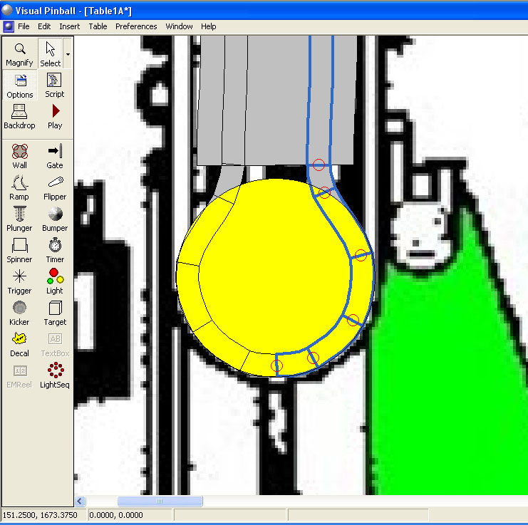
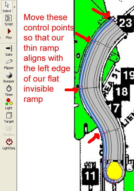
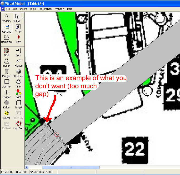
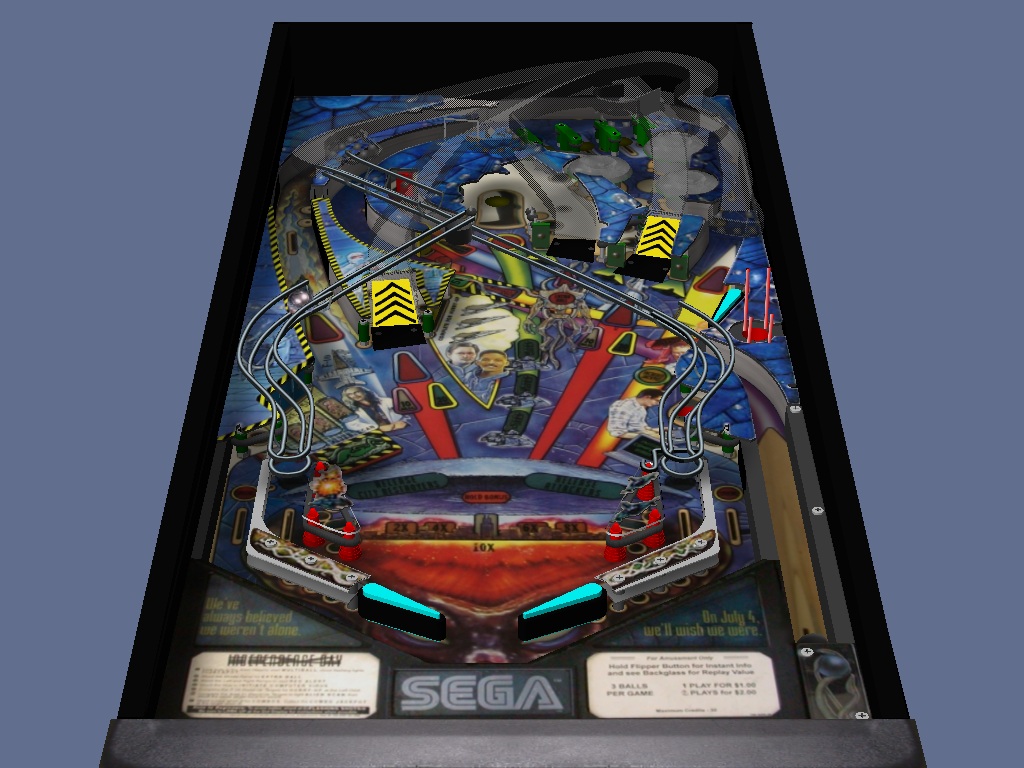
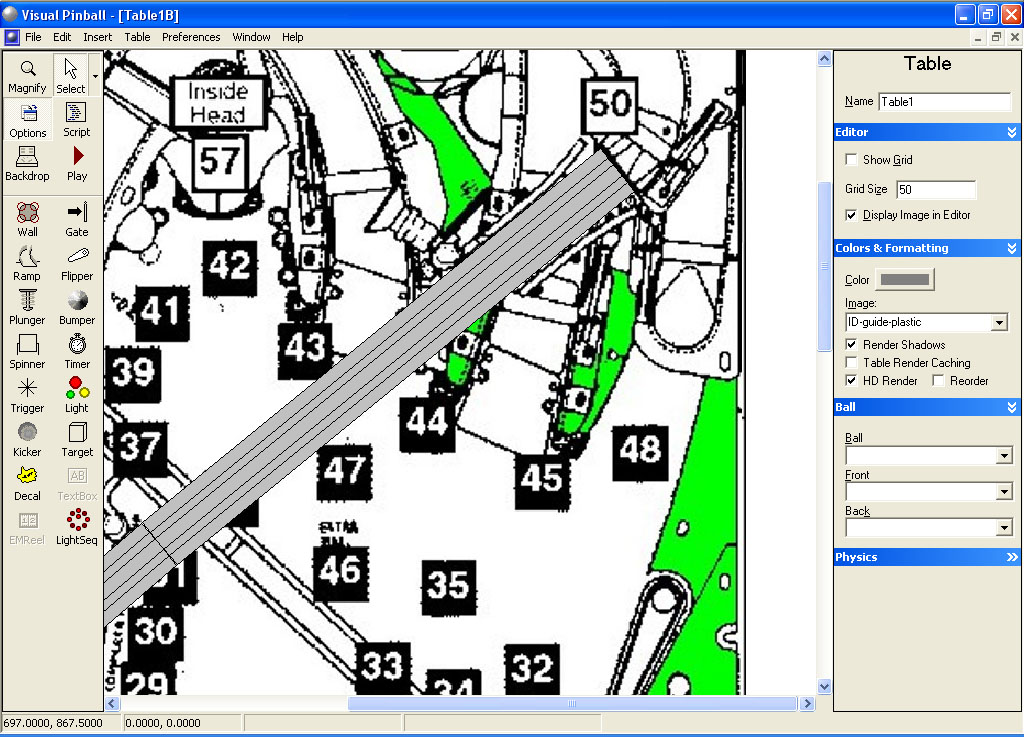
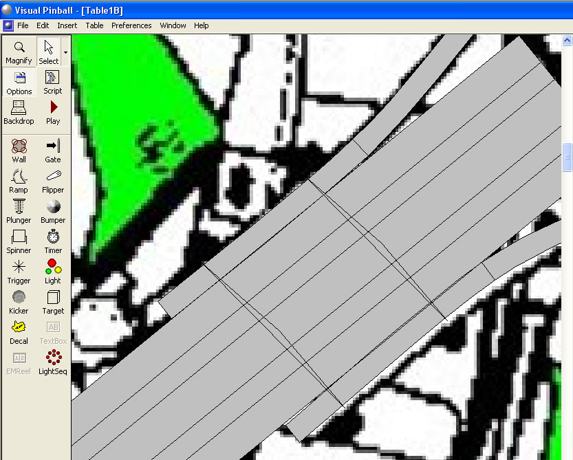
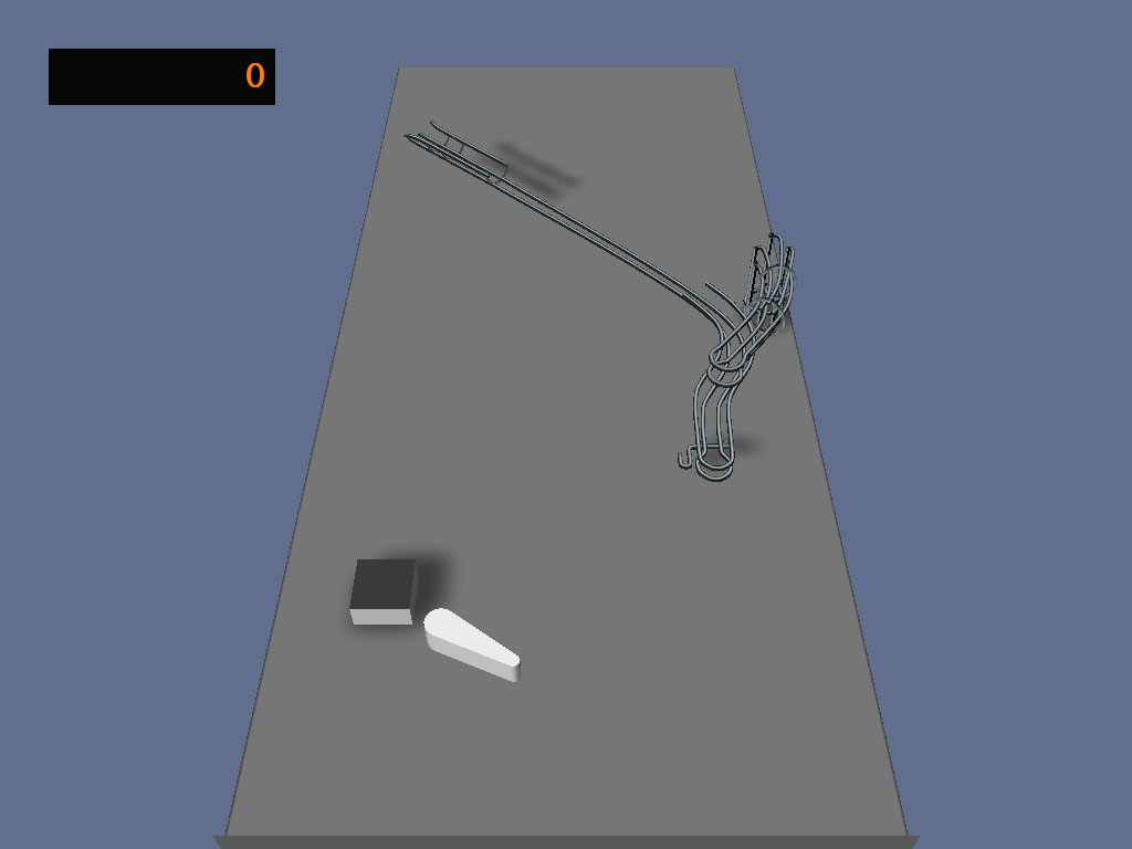
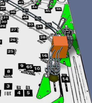
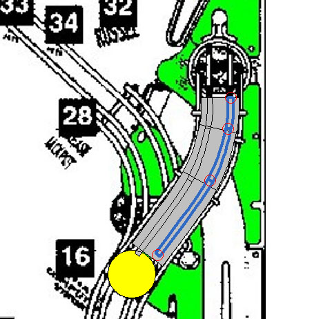
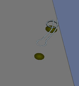
Take a look at the following picture:


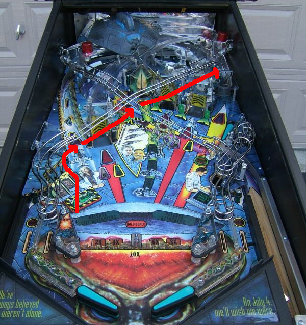
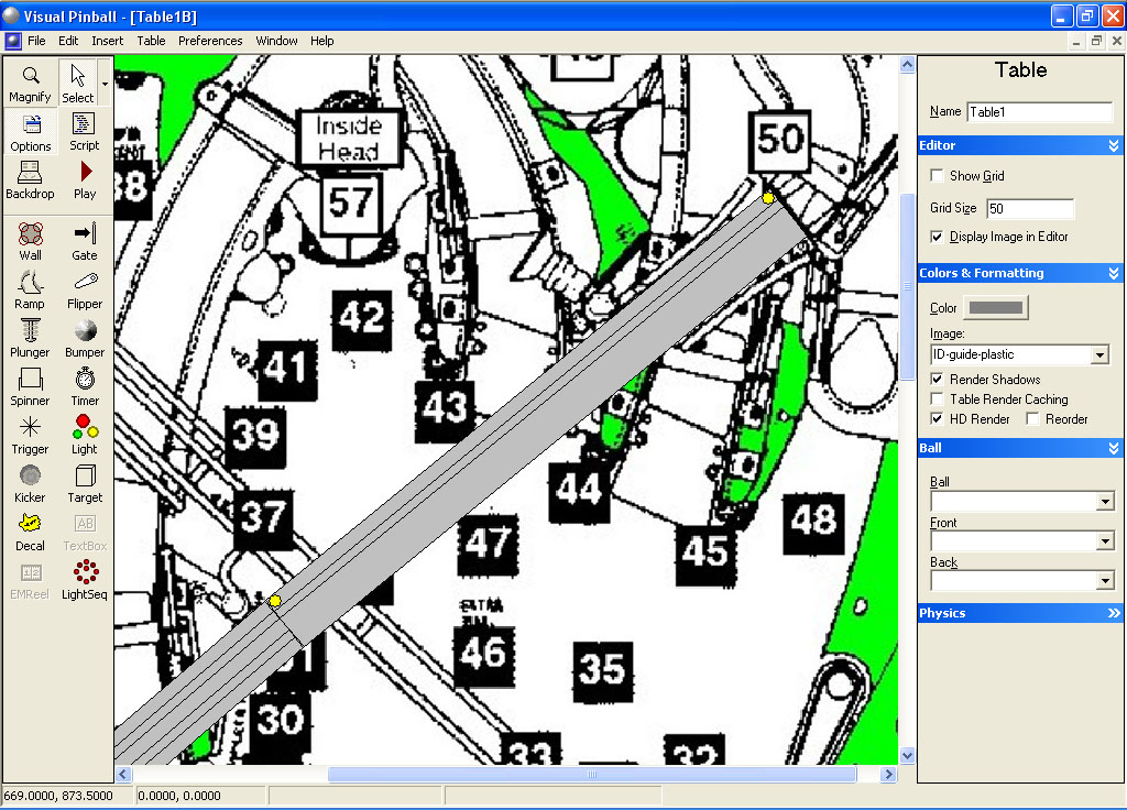
We will be building the ramp in three sections. Do like you did before for the first ramp (make a new table, import the ID guide plastic image and change the table height to 2300). If you did this for building the first wire ramp, you can actually use the same table file to build this new left ramp.

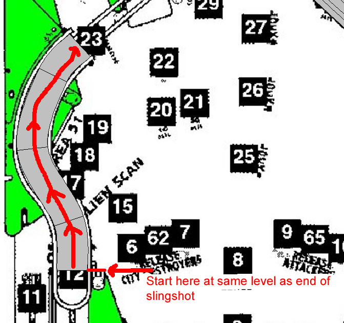
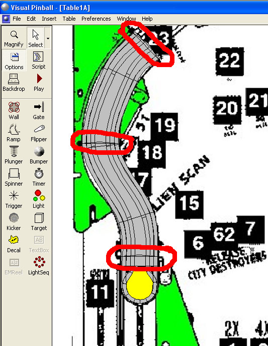
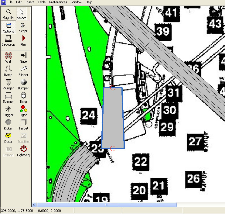
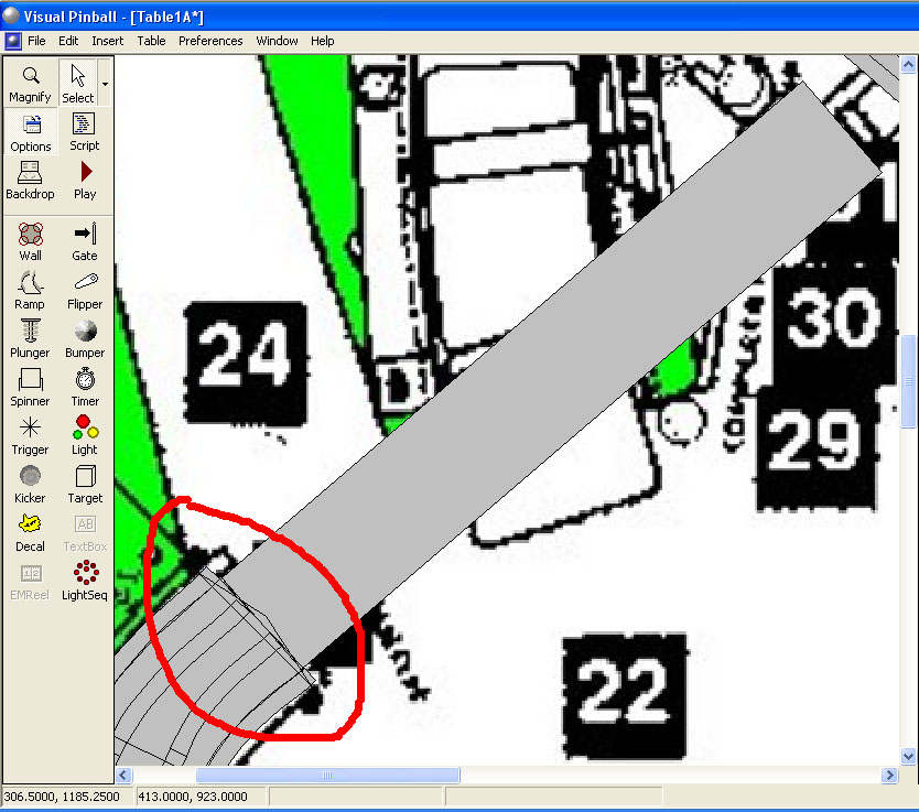
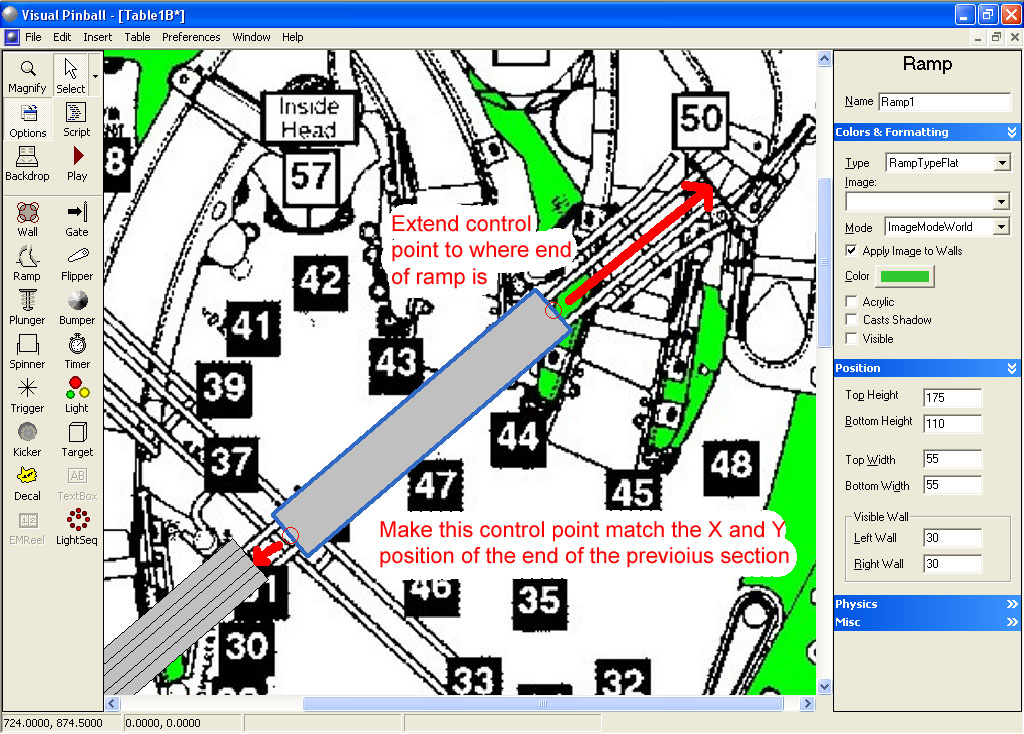
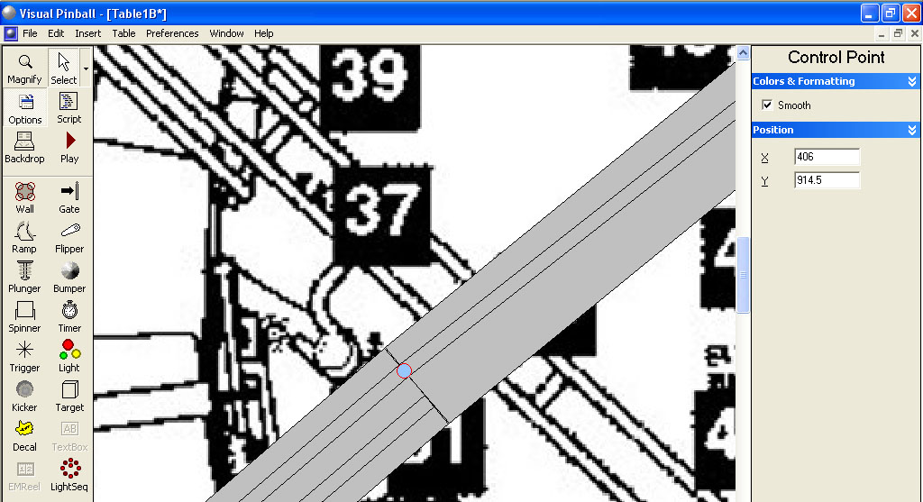
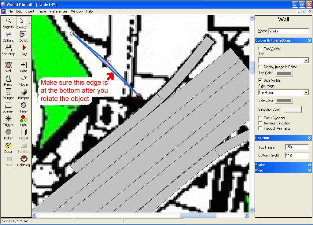
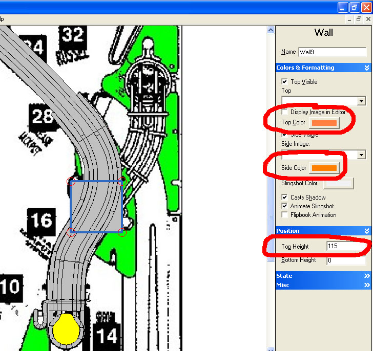
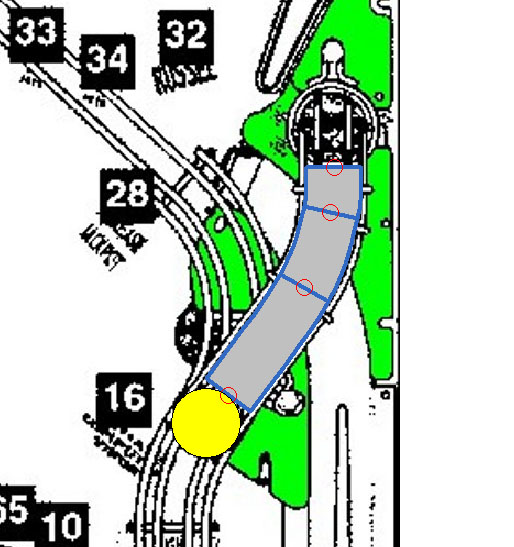
For the first section, make a ramp starting at the same level as the end of the slingshot plastic and end right at the “23” in the black square. Make sure the direction of the ramp matches the picture (the ramp bottom is at the bottom of the screen and the ramp top is at the top. The ramp will not work properly if the direction of the ramp is wrong). Add control points to the ramp (right click inside the ramp and left click on add point) as necessary to match the same shape from our guide image:


Set the ramp top and bottom width 55. Change the bottom height to 60 and top to 110. Unckeck both Cast Shadow and Visible.


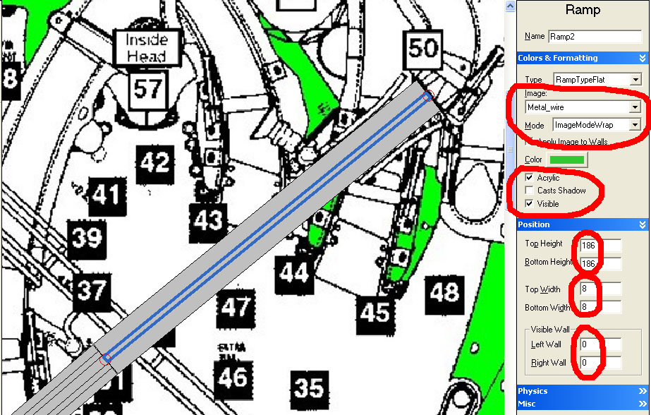
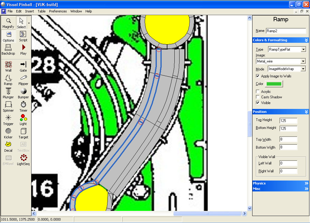
Now with the ramp highlighted, make a copy (hit CTRL-C or Edit Copy) then paste (CTRL-V or Edit Paste). Change this copied ramp top and bottom width to 8, Visible Wall left and right to 0, Bottom height to 71 (11 units higher than our ramp floor bottom height) and top height to 121 (11 units higher than our ramp floor top height). Click on Visible and Acrylic so it will show up. Select your Metal_wire as the ramp image and set the Mode to ImageModeWrap. Under physics, un-check Collidable (otherwise the ball won’t travel on the ramp)

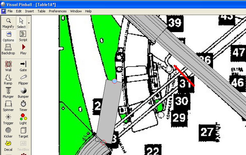
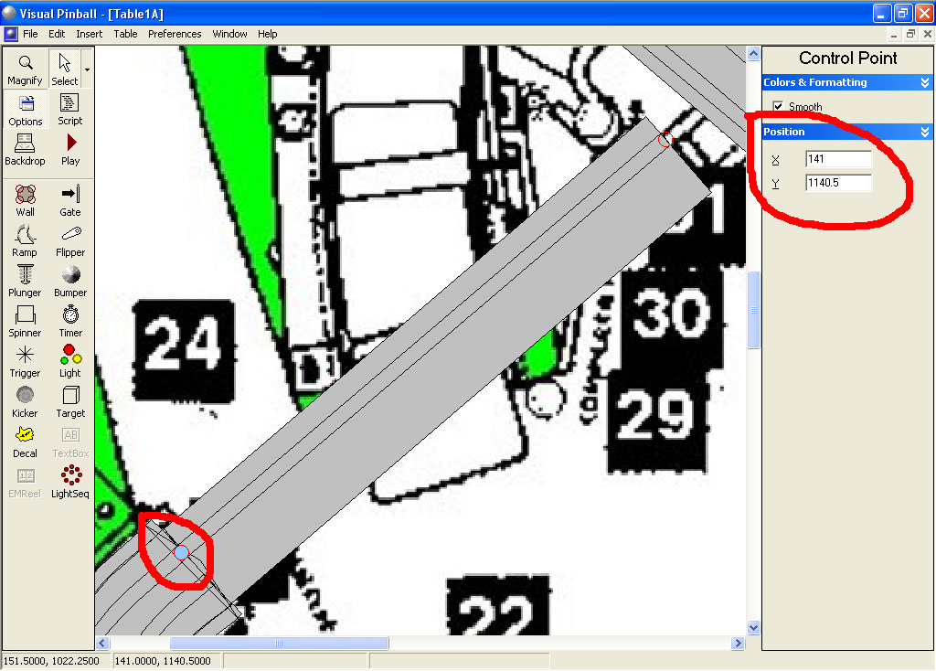
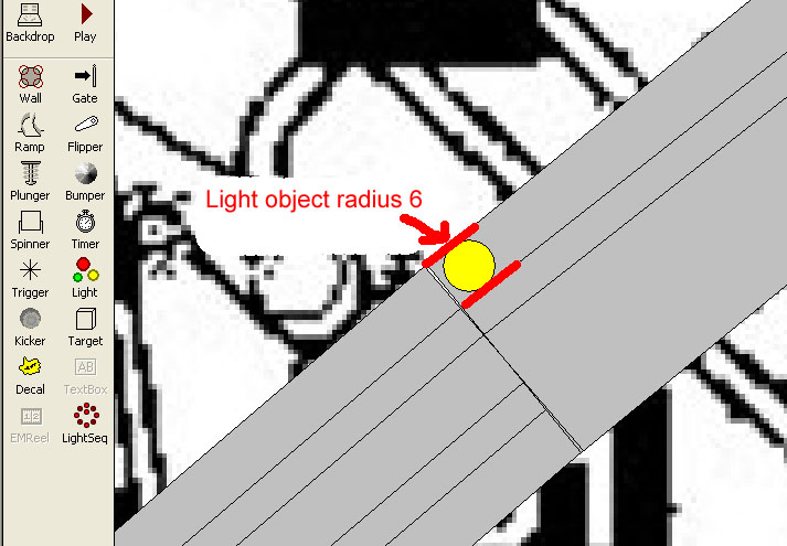
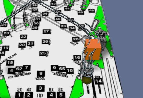
Now right click on this new ramp and translate it -15. If you add a light object of radius 4 to the left edge of the first wide ramp object, your new narrow ramp should line up on the right edge of that light object.

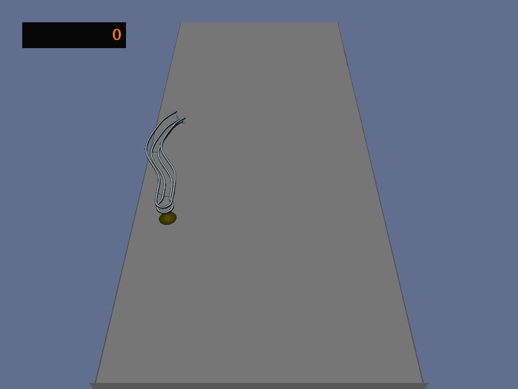
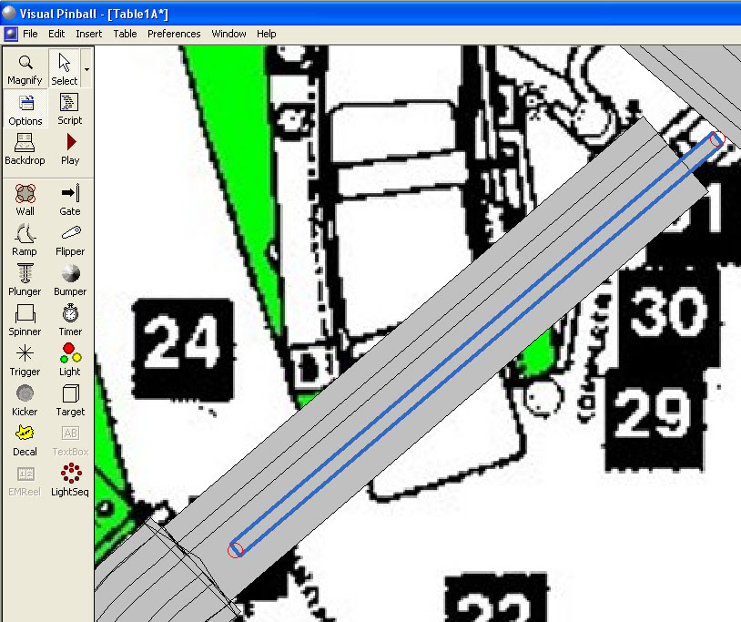
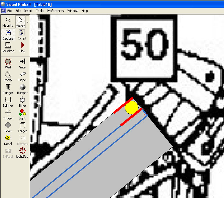
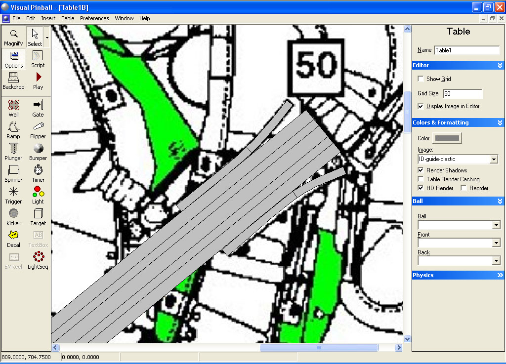
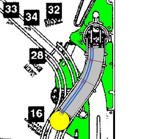
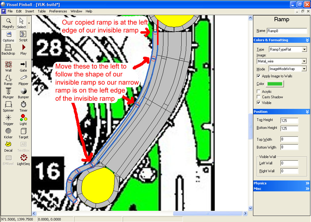
Make another copy of the thin ramp and translate it in the X direction by 30. Your ramp should now look like this:


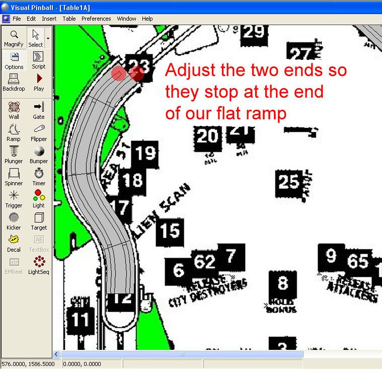
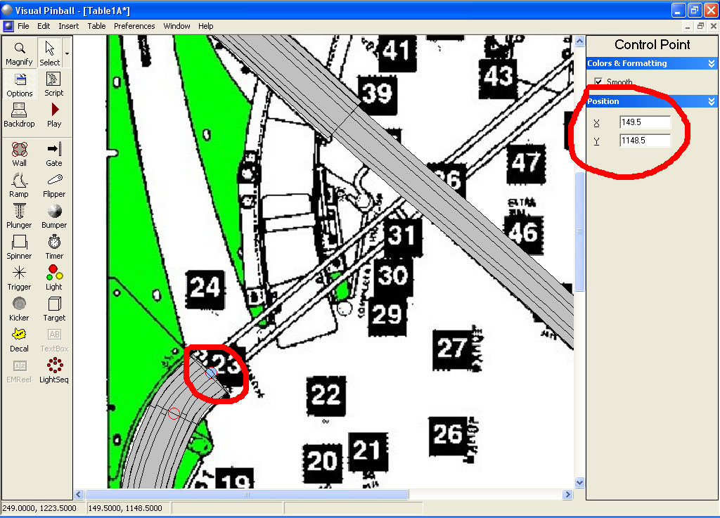
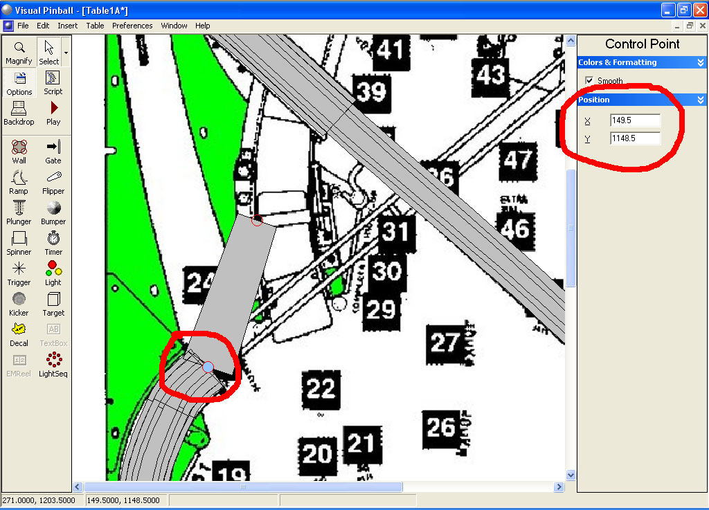
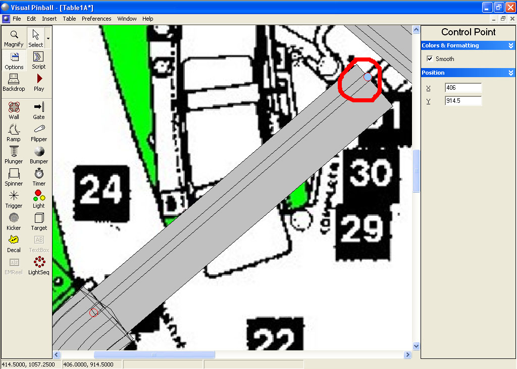
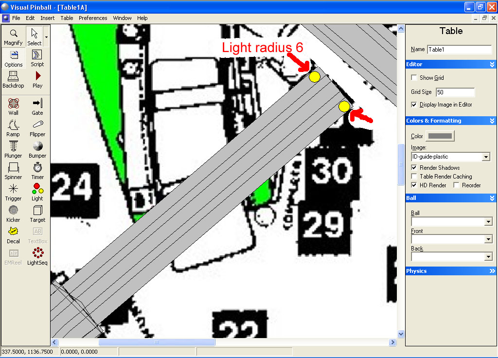
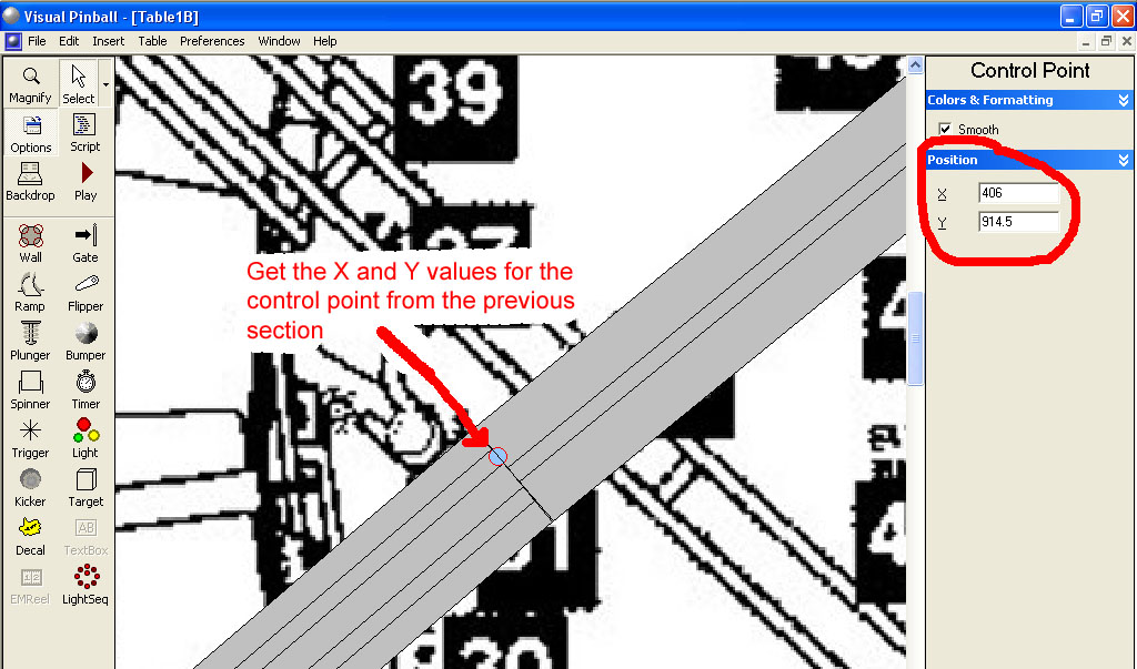
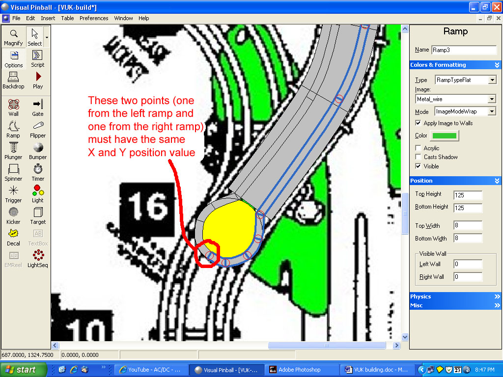
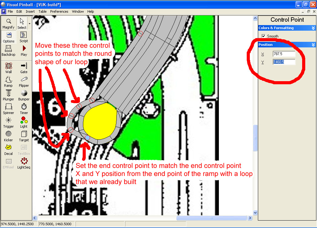
Adjust the top end control point of both small ramps to match the end of our ramp floor.

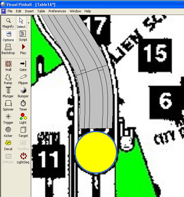
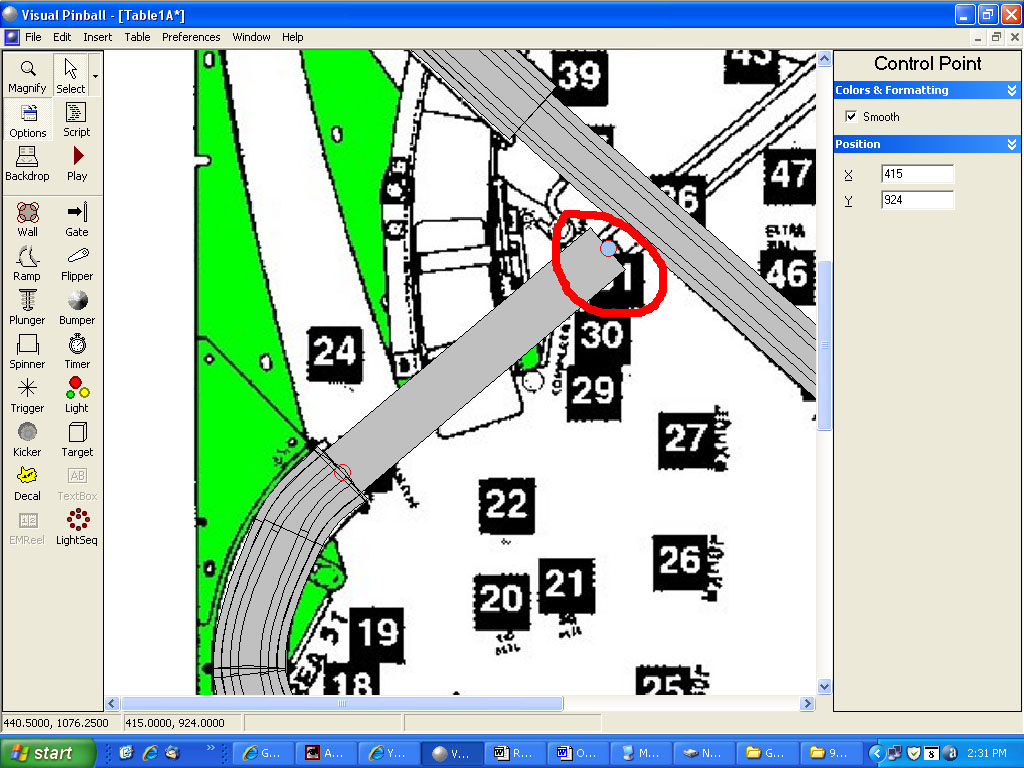
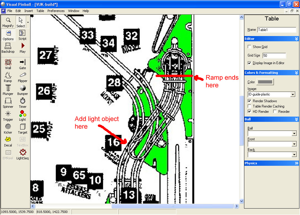
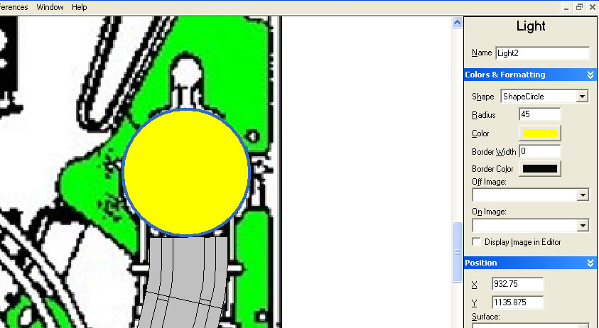
Now add a light object of radius 35 to the end of the ramp (this will be our guide for the ramp end).


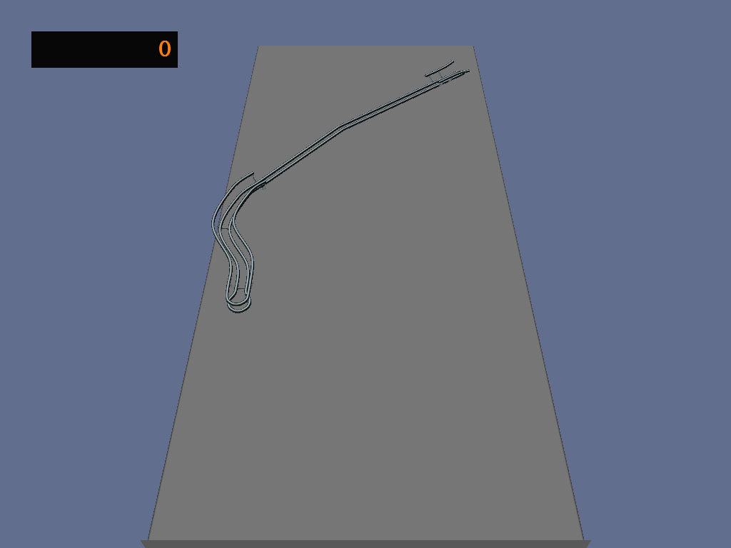
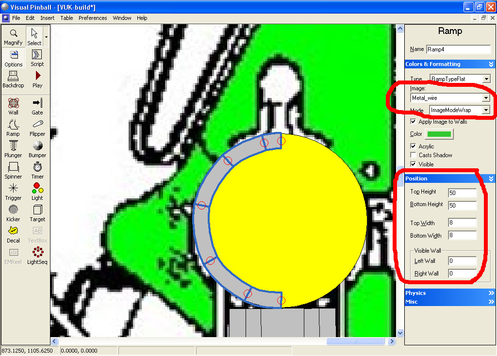
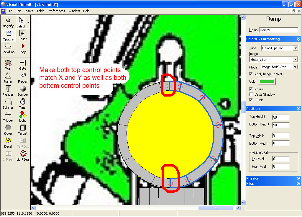
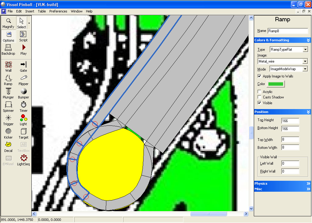
Now repeat the same process as we did before for the right ramp to form the left half of the loop then do as before to create the right half. When you are finished it should look like this:


Now make a copy of the left narrow ramp. Change the Visible Wall to 6 for both left and right, change the bottom height to 65, top height to 115. Select None for the image and click on the color button and change the Red value to 45, Green to 51 and Blue to 51. Repeat for the right narrow ramp. This will give the bottom of the wire a black shadow.


Now that we’ve build the metal wire for the base of the ramp, we need to build the outer walls.

Start by making a copy of the left wire that has the metal image. Click on it to select it. If you are having trouble selecting it, you can move the flat ramp out of the way, then click on the left wire ramp to select it, then hit CTRL-Z (or Edit, Undo). This will move the flat ramp back into position and leave metal wire still highlighted.

With the new ramp still selected, translate it -16 in the X position:


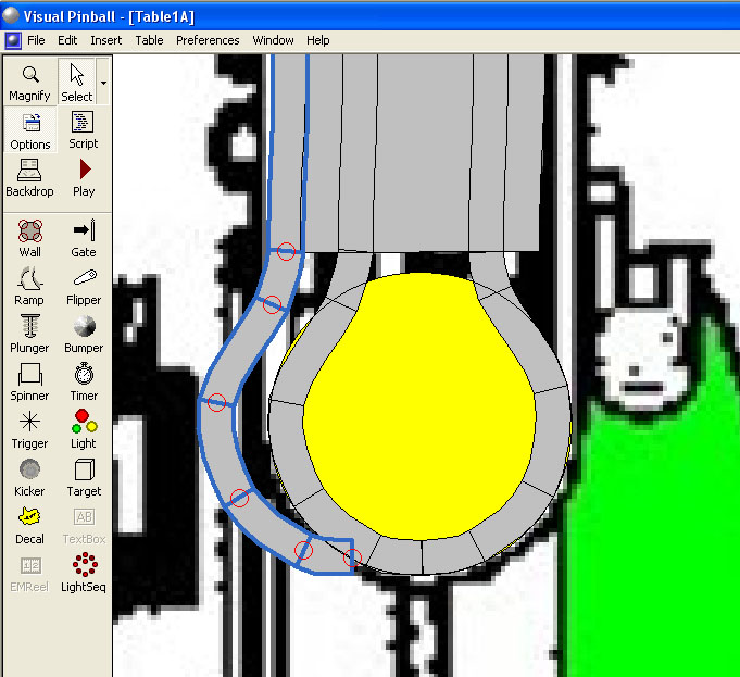
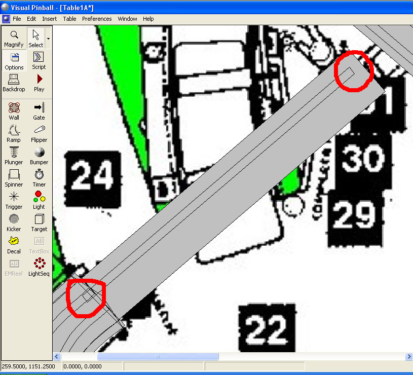
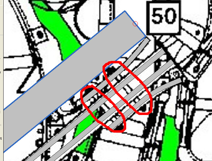
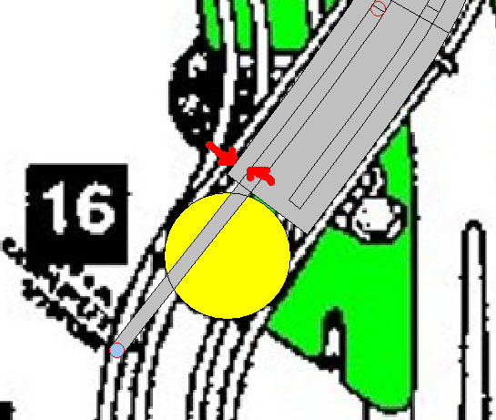
Now we need to re-shape the end. Refer to the image below:


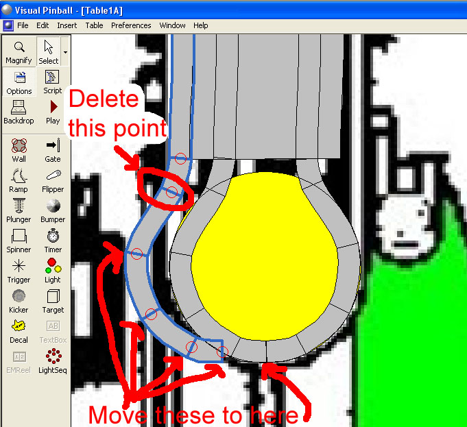
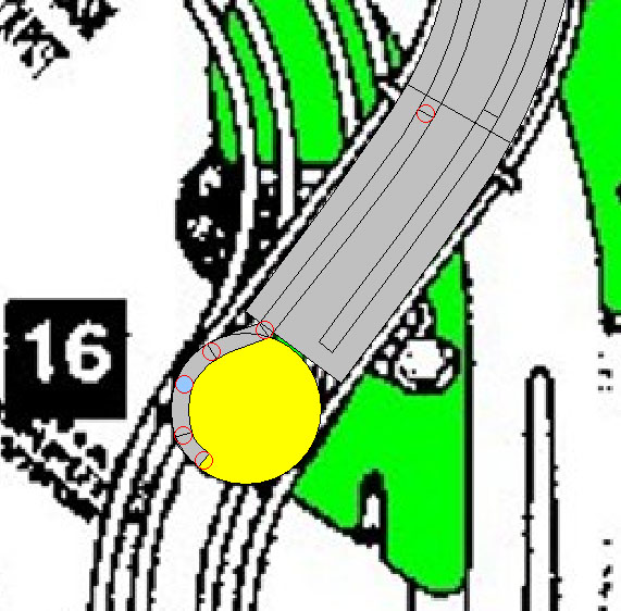
Delete the control point indicated. Then select the other control points indicated (click on one, hold the shift key, click on the next and so on) and move them to the right so that the end one is at the bottom center of our loop. The move can be accomplished by using the right arrow key on the keyboard to move all the selected control points together. Keep hitting the right arrow key until all is in the right place (should take about 32 hits of the key). When done it should look like this:


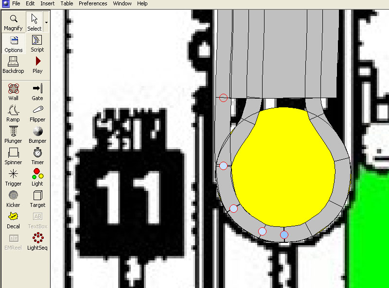
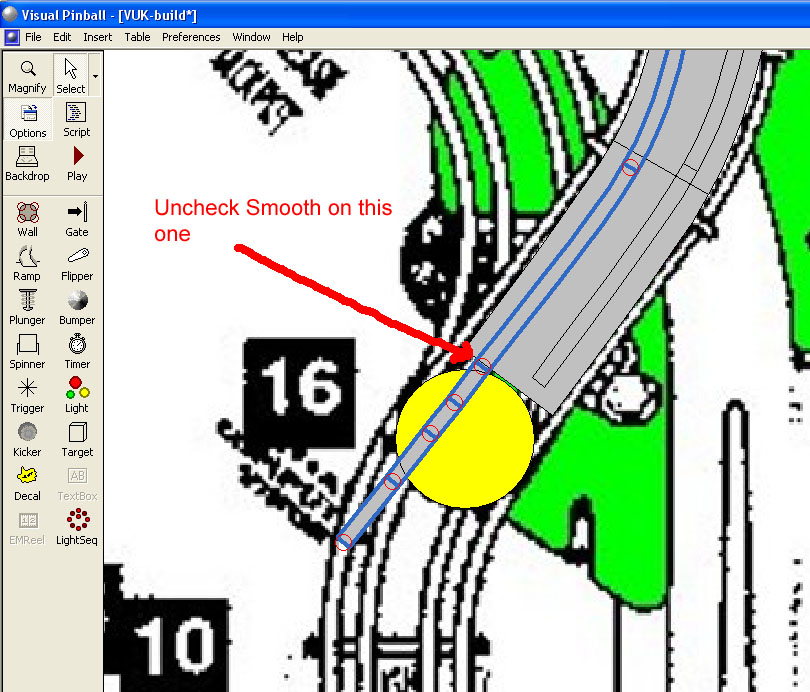
Now we start moving control points so that our new outer wire ramp aligns with the left edge of our invisible floor ramp. Start towards the bottom and work your way up the ramp until you are done:


Now with our new ramp still selected change the bottom height to 101 and the top height to 151.

Make a copy of this ramp and paste it (CTRL-C and then CTRL-V). Change the Image to None, Color to R=45, G=51, and B=51, Top height to 145 (6 units below the same ramp with the metal wire texture), Bottom height to 95, and Left and Right wall to 6 for both.

Repeat this same process to build the right side.

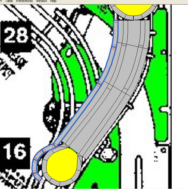
Add three ramp rings. The bottom one will have the same top and bottom height as in our right ramp that we already built (bottom=56, top=96), our middle ring should be bottom=90, top=130, and our top ring bottom=101, top=141.
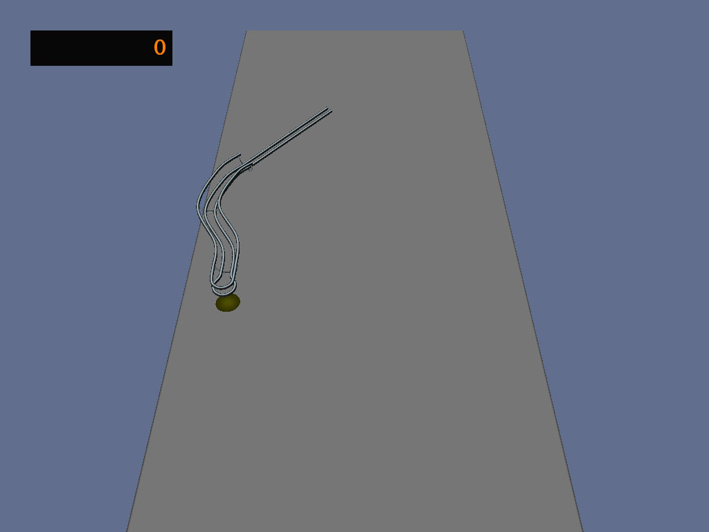
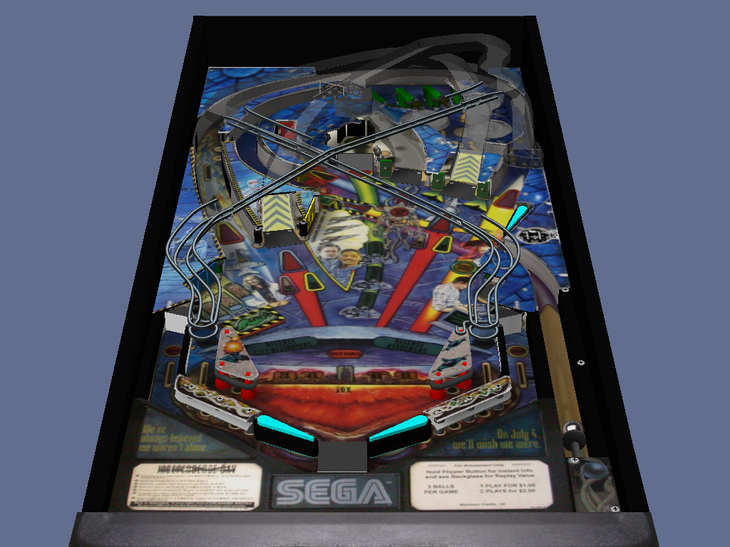
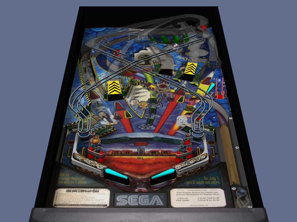
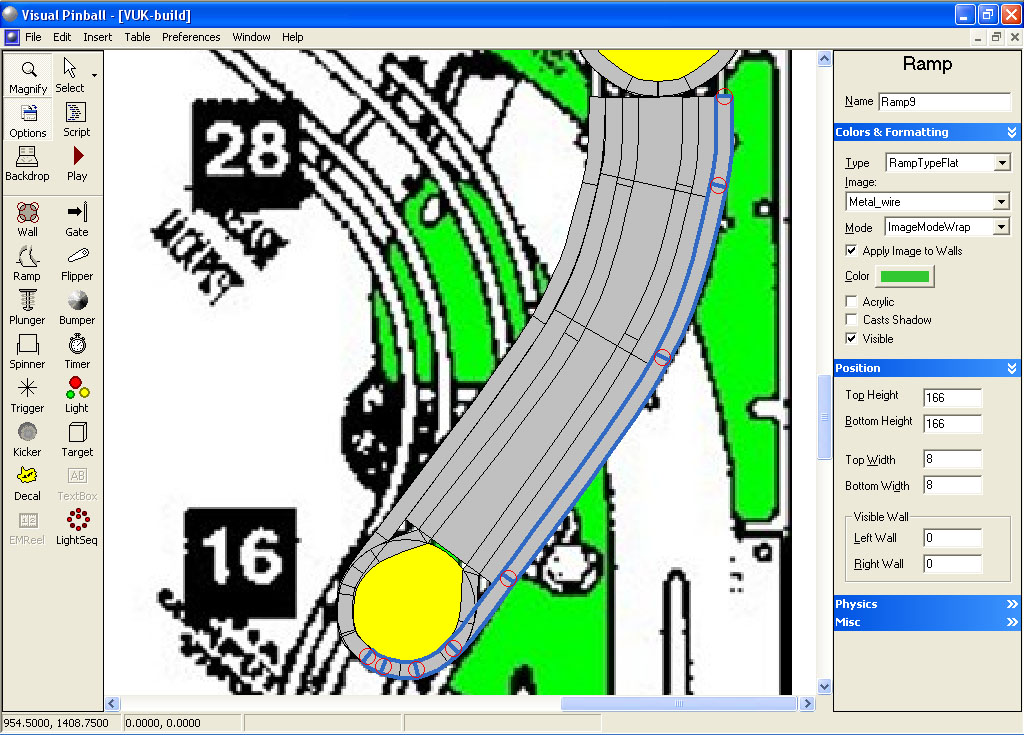


That’s it for the first section. Your ramp should look like this:


#262 kruge99

kruge99

    Pinball Wizard

  • VPF Staff
  • 3,901 posts
  • Location:Markham, Ont.

  • Flag: Canada

  • Favorite Pinball: Black Knight, High Speed and Pin*Bot


Posted 01 January 2010 - 02:33 PM

Great! A new tutorial and I don't know if I'll have time to work on it before I go out of town for the weekend! ohmy.gif LoL! I hope everyone has a Happy New Year!


Best Regards,
Todd.

[proud owner of a Williams Solar Fire]

- It's called "The American Dream" because you have to be asleep to believe it.
George Carlin
- Truly great madness cannot be achieved without significant intelligence.
Henrik Tikkanen
- "Reality check, Michelle, Talk about composure, Total lack of. He's a man-- About-- 12 Feet Tall--"
Carrie Kelly
Posted Image

#263 wtiger

wtiger

    Pinball Fan

  • VIP
  • 1,148 posts
  • Location:Los Angeles, CA

  • Flag: United States of America

  • Favorite Pinball: Junkyard


Contributor

Posted 09 January 2010 - 12:48 AM

On to the second section.

This second section will be fairly simple as it is just a straight section going from bottom height of 110 to a top height of 175.

Start out by loading in your table where you started making the left ramp and click on the flat ramp from the first section you built. Now click on the very end control point and write down the X and Y coordinates. We will use this information to line up the bottom of the next section to it:


Add a ramp to your table near where it needs to go:


Now click on the lower control point of this ramp we just added and enter the X and Y values you wrote down from the end of the previous ramp section:


Change the ramp bottom and top width to 55. Change the bottom height to 110 and the top height to 175. Uncheck Visible and Cast Shadows. We will be moving the top control point to where the red line is:


Now grab the top control point of the ramp we just added and move it into position:


Zoom in a bit where this ramp meets the end of the previous section to make sure that it lines up pretty good without any gaps. If you see any gaps, adjust the upper control point a bit to eliminate the gaps. Below is an example of too much gap:


This is what you want it to look like:


Make sure the ramp is selected (click on it) and make a copy (CTRL-C or Edit Copy) then paste (CTRL-V or Edit Paste). Change this copied ramp top and bottom width to 8, Visible Wall left and right to 0, Bottom height to 121 (11 units higher than our ramp floor bottom height) and top height to 186 (11 units higher than our ramp floor top height). Click on Visible and Acrylic so it will show up. Select your Metal_wire as the ramp image and set the Mode to ImageModeWrap. Under physics, un-check Collidable (otherwise the ball won’t travel on the ramp)

Now right click on this new ramp and translate it -15 in the X direction. You will notice that the bottom of our thin ramp overlaps with the thin ramp it’s connecting with and the top falls a little short of the end of our floor ramp:


We must manually adjust the top and bottom control points so they line up properly. Grab the top control point and move it into position so that the end matches the end of our floor ramp:


For the bottom control point, get the X and Y position of the ramp we are lining up with and plug those coordinates into the bottom control point:


Now make a copy of the narrow ramp. Change the Visible Wall to 6 for both left and right, change the bottom height to 115 and the top height to 180 (the bottom and top are 6 units below the ramp we copied from). Select None for the image and click on the color button and change the Red value to 45, Green to 51 and Blue to 51. This will give the bottom of the wire a black shadow.

Now make a copy of one of the thin ramps and translate the copy in the X direction 30 units.


Once again we need to manually adjust the top and bottom control points. For the top control point, move it down so the end of the ramp is where our floor ramp ends. For the bottom control point, again, match it up with the X and Y coordinates of the ramp we are lining it up with. Note: If you add a light object of radius 6 that seems to be about the right width that our narrow ramp should be in from the edge (left and right) of our floor ramp:


Now, make a copy of this right narrow ramp. Depending on which one you copied, make the appropriate adjustment for the ramp bottom and top height, visible wall left and right, and image/color.

When you are done, your ramp should look like this:


#264 kruge99

kruge99

    Pinball Wizard

  • VPF Staff
  • 3,901 posts
  • Location:Markham, Ont.

  • Flag: Canada

  • Favorite Pinball: Black Knight, High Speed and Pin*Bot


Posted 19 January 2010 - 01:27 AM

Heya!! I finally had enough time to get back into this WIP so here is my progress!! I hope wtiger you are ready to continue soon. I'm sorry I was distracted by my Avro Arrow Tribute table and the King Tut MOD table to finish up these last two steps.


Best Regards,
Todd.


[proud owner of a Williams Solar Fire]

- It's called "The American Dream" because you have to be asleep to believe it.
George Carlin
- Truly great madness cannot be achieved without significant intelligence.
Henrik Tikkanen
- "Reality check, Michelle, Talk about composure, Total lack of. He's a man-- About-- 12 Feet Tall--"
Carrie Kelly
Posted Image

#265 neoblood

neoblood

    Enthusiast

  • Charter Member
  • 381 posts
  • Location:USA

  • Flag: United States of America

  • Favorite Pinball: bop

Posted 19 January 2010 - 01:39 AM

Looking good, looks like it'll take me a year to catch back up ! biggrin.gif
A Pinball a day takes the boredom away

#266 wtiger

wtiger

    Pinball Fan

  • VIP
  • 1,148 posts
  • Location:Los Angeles, CA

  • Flag: United States of America

  • Favorite Pinball: Junkyard


Contributor

Posted 19 January 2010 - 02:07 AM

Looking good Todd. I appreciate you keeping us posted on your progress! Here's the next section:

The third and final section

This last section of the ramp will also be fairly simple (like the previous section) but will have a couple more elements to it than just the straight section.

To save some time, we can copy the invisible floor ramp from the previous section and line up the bottom control point to match the previous section and then just extend the top control point. Set the bottom height to 175 (the top height should already be at 175).


Now copy then paste. Set the top and bottom width to 8, top and bottom height to 186 (once again, 11 units higher than our floor ramp height of 175), Visible wall to 0 for left and right, uncheck colladible, put a check in Acrylic and Visible, change the Image to Metal_wire and the mode to ImageModeWrap (these settings are all the same as we did in the previous two sections except for the top and bottom height).


Now get the X and Y values of the end control point from the previous section:


Manually change the X and Y of the bottom control point of the ramp we just added:


Now if you add a light object of radius 6 just inside our invisible floor ramp it will fit approximately between our invisible floor ramp and the narrow wire ramp we just added:


Now add a light object of radius 6 at the end of our ramp and adjust the control point of our narrow wire ramp:


Now make a copy of the narrow ramp. Change the Visible Wall to 6 for both left and right, change the bottom and top height to 180 (the bottom and top are 6 units below the ramp we copied from). Select None for the image and click on the color button and change the Red value to 45, Green to 51 and Blue to 51. This will give the bottom of the wire a black shadow.


Now repeat this process for the right side. Your ramp should look like this (I deleted my reference circles):


Now add the flared portion at the left and right end of our ramp. For the ramp with the Metal_wire image use a top and bottom height of 215 (40 units higher than our invisible floor ramp height of 175). For the ramp acting as our black shadow, the top and bottom height are both 209 (6 units lower than the Metal_wire ramp). Your ramp should look like this:


Now all we need to do is add two metal half rings and we’ll be done.

If you move the invisible ramp out of the way you will see where the two rings go:


Now copy one of the rings from your previous ramp that you build and rotate it making sure the proper side/edge is at the bottom and move it into the approximate location. Change the bottom height to 175 and the top height to 215 (the bottom height matches the height of our invisible floor ramp and the top height is 40 units higher than that):


Now move it into position, make a copy and move that into position. When you are done it should look like this:


Now your finished ramp should look like this:


All that’s left now is to copy all the elements and paste them into your ID table. You might need to do a little adjusting where the transparent ramp meets the wire ramp. Your ID table should now look something like this:


Now copy from the lower portion of the right ramp the two objects that make up the piece that connects the ramp to the right sling. Flip it and move it into position for the left side. We should have actually done this before we pasted our left ramp into our ID table, but that’s OK, we can do it now.

Next up will be the VUK (Verticle Up Kicker)…


#267 kruge99

kruge99

    Pinball Wizard

  • VPF Staff
  • 3,901 posts
  • Location:Markham, Ont.

  • Flag: Canada

  • Favorite Pinball: Black Knight, High Speed and Pin*Bot


Posted 19 January 2010 - 02:52 AM

You were waiting in the shadows to spring this next tutorial on us!! Damn, I'm too tired to wrap this up tonight, I'll have to work on it tomorrow wtiger!! biggrin.gif


Best Regards,
Todd.
[proud owner of a Williams Solar Fire]

- It's called "The American Dream" because you have to be asleep to believe it.
George Carlin
- Truly great madness cannot be achieved without significant intelligence.
Henrik Tikkanen
- "Reality check, Michelle, Talk about composure, Total lack of. He's a man-- About-- 12 Feet Tall--"
Carrie Kelly
Posted Image

#268 faralos

faralos

    VPF Veteran

  • Members
  • PipPipPipPipPipPip
  • 7,838 posts
  • Location:Eastern Pa,USA

  • Flag: United States of America

  • Favorite Pinball: Flash (Williams) 1979, Flash2 Updated


  • Trophies:

Posted 19 January 2010 - 03:36 AM

wow! are you guys still building this one? I lost all I had done last year when my computer died, but I really want to learn vertical kickers! So I'll be looking in every now and then. Sorry i can't be here building this one anymore, I just do originals in VP9 now with the 'Gas Attack' pin wip being the one exception. although that is being done in vp9 also, it's based on a real pin. sorry for bringing that up here didn't mean to cut in...just letting you know I'm still here in spirit, looking really cool though, wish I knew how you made your ramps look so real (Truespace?)
"Don’t let the noise of others’ opinions drown out your own inner voice.
And most important, have the courage to follow your heart and intuition.”
----Steve Jobs


#269 kruge99

kruge99

    Pinball Wizard

  • VPF Staff
  • 3,901 posts
  • Location:Markham, Ont.

  • Flag: Canada

  • Favorite Pinball: Black Knight, High Speed and Pin*Bot


Posted 19 January 2010 - 01:36 PM

Actually Faralos, the individual wires of the ramps are made up of two narrow ramps on top of each other. The top narrow ramp has the "wire" image and the ramp right under it is a dark colour to make it look "thicker". The wire ramps have their "collide-able" check box empty. Then there is one invisible, flat ramp, underneath the "wire" ramps to carry the ball. No Truespace models were harmed during the creation of these ramps. wink.gif


Best Regards,
Todd.

[proud owner of a Williams Solar Fire]

- It's called "The American Dream" because you have to be asleep to believe it.
George Carlin
- Truly great madness cannot be achieved without significant intelligence.
Henrik Tikkanen
- "Reality check, Michelle, Talk about composure, Total lack of. He's a man-- About-- 12 Feet Tall--"
Carrie Kelly
Posted Image

#270 kruge99

kruge99

    Pinball Wizard

  • VPF Staff
  • 3,901 posts
  • Location:Markham, Ont.

  • Flag: Canada

  • Favorite Pinball: Black Knight, High Speed and Pin*Bot


Posted 19 January 2010 - 04:17 PM

Here is my finished wire ramps!


Best Regards,
Todd.

[proud owner of a Williams Solar Fire]

- It's called "The American Dream" because you have to be asleep to believe it.
George Carlin
- Truly great madness cannot be achieved without significant intelligence.
Henrik Tikkanen
- "Reality check, Michelle, Talk about composure, Total lack of. He's a man-- About-- 12 Feet Tall--"
Carrie Kelly
Posted Image

#271 wtiger

wtiger

    Pinball Fan

  • VIP
  • 1,148 posts
  • Location:Los Angeles, CA

  • Flag: United States of America

  • Favorite Pinball: Junkyard


Contributor

Posted 20 January 2010 - 04:14 AM

Very nice Todd! cool.gif


#272 kruge99

kruge99

    Pinball Wizard

  • VPF Staff
  • 3,901 posts
  • Location:Markham, Ont.

  • Flag: Canada

  • Favorite Pinball: Black Knight, High Speed and Pin*Bot


Posted 20 January 2010 - 11:20 AM

Thanks!! btw - I had to raise the glass height to 226 from 225 otherwise the ball would fall off the new/last wire ramp that was 175 height. Strange?


Best Regards,
Todd.

[proud owner of a Williams Solar Fire]

- It's called "The American Dream" because you have to be asleep to believe it.
George Carlin
- Truly great madness cannot be achieved without significant intelligence.
Henrik Tikkanen
- "Reality check, Michelle, Talk about composure, Total lack of. He's a man-- About-- 12 Feet Tall--"
Carrie Kelly
Posted Image

#273 wtiger

wtiger

    Pinball Fan

  • VIP
  • 1,148 posts
  • Location:Los Angeles, CA

  • Flag: United States of America

  • Favorite Pinball: Junkyard


Contributor

Posted 23 January 2010 - 12:15 AM

I've been playing around a bit today with the VUK. I've never done one in VP before, so I have no idea how it's going to work out. I will be looking heavily at Lords of the Rings to see how it was done for that table when the time comes (which may also cause us to re-model ours but we'll see). Here's what I came up with. Does it look acceptable for a VUK?


#274 kruge99

kruge99

    Pinball Wizard

  • VPF Staff
  • 3,901 posts
  • Location:Markham, Ont.

  • Flag: Canada

  • Favorite Pinball: Black Knight, High Speed and Pin*Bot


Posted 23 January 2010 - 02:52 AM

c00L!! it sorta looks like the Queen from Aliens!!

is it difficult to make?


Best Regards,
Todd.
[proud owner of a Williams Solar Fire]

- It's called "The American Dream" because you have to be asleep to believe it.
George Carlin
- Truly great madness cannot be achieved without significant intelligence.
Henrik Tikkanen
- "Reality check, Michelle, Talk about composure, Total lack of. He's a man-- About-- 12 Feet Tall--"
Carrie Kelly
Posted Image

#275 faralos

faralos

    VPF Veteran

  • Members
  • PipPipPipPipPipPip
  • 7,838 posts
  • Location:Eastern Pa,USA

  • Flag: United States of America

  • Favorite Pinball: Flash (Williams) 1979, Flash2 Updated


  • Trophies:

Posted 23 January 2010 - 03:53 AM

i just learned the coding for the vuk's from theguyoverthere, (nothing like a little PI every now and then!) now how did you make that ramp?
"Don’t let the noise of others’ opinions drown out your own inner voice.
And most important, have the courage to follow your heart and intuition.”
----Steve Jobs


#276 wtiger

wtiger

    Pinball Fan

  • VIP
  • 1,148 posts
  • Location:Los Angeles, CA

  • Flag: United States of America

  • Favorite Pinball: Junkyard


Contributor

Posted 23 January 2010 - 05:37 PM

I don't think it is too difficult to make (it's pretty much the same as the previous wire ramps we built). I have no idea yet how well it will work for a VUK but worst case we can fake it with kickers so the ball appears to move up through it (this is way down the road still). I'll do the write up on it in a little bit (my wife and I are on our way out for a walk on the beach - well, the bike path). One of the other options I was thinking about is creating this in Future Pinball, take a snaphot and using a portion of that (for the back part). I'm flexible, so if anything needs to be changed later, no problem. If someone comes up with better/different idea for anything related to this table, just post it.

#277 wtiger

wtiger

    Pinball Fan

  • VIP
  • 1,148 posts
  • Location:Los Angeles, CA

  • Flag: United States of America

  • Favorite Pinball: Junkyard


Contributor

Posted 24 January 2010 - 04:56 AM

I got a late start on the write up (I'm about 1/4 done). I'll have it finished and posted tomorrow.

#278 kruge99

kruge99

    Pinball Wizard

  • VPF Staff
  • 3,901 posts
  • Location:Markham, Ont.

  • Flag: Canada

  • Favorite Pinball: Black Knight, High Speed and Pin*Bot


Posted 24 January 2010 - 01:49 PM

Thanks! I tried to figure it out from your screenshot, but it's kind of difficult to see the makings of the wires. I can't wait to see how it's done.


Best Regards,
Todd.


[proud owner of a Williams Solar Fire]

- It's called "The American Dream" because you have to be asleep to believe it.
George Carlin
- Truly great madness cannot be achieved without significant intelligence.
Henrik Tikkanen
- "Reality check, Michelle, Talk about composure, Total lack of. He's a man-- About-- 12 Feet Tall--"
Carrie Kelly
Posted Image

#279 faralos

faralos

    VPF Veteran

  • Members
  • PipPipPipPipPipPip
  • 7,838 posts
  • Location:Eastern Pa,USA

  • Flag: United States of America

  • Favorite Pinball: Flash (Williams) 1979, Flash2 Updated


  • Trophies:

Posted 24 January 2010 - 04:10 PM

my guess would be to make a ramp(or two?) with a base height of 0 in front and behind the actual vuk to simulate a wire enclosure of sorts coming up from the table surface, I've yet to try it though as I've been busy trying to finish the Gas Attack wip to get it up here by tonite. that would be for my next wip anyhow, I was just wondering how to do it.
"Don’t let the noise of others’ opinions drown out your own inner voice.
And most important, have the courage to follow your heart and intuition.”
----Steve Jobs


#280 wtiger

wtiger

    Pinball Fan

  • VIP
  • 1,148 posts
  • Location:Los Angeles, CA

  • Flag: United States of America

  • Favorite Pinball: Junkyard


Contributor

Posted 24 January 2010 - 08:47 PM

VUK building – Part 1
(I decided to break this up into several parts since it was getting a little long)


Below is a reference picture with three images of the VUK to use for reference:


Load in your temporary table you’ve been using to build the wire ramps from. To start out we need to figure out what the minimum height we can use for our VUK so that a ball traveling on the ramp right below will have enough clearance. What I did is add a wall object to the table and moved it to where the majority of our VUK overlaps the ramp below. I changed the top and side color of the wall to orange so it stands out. For starters I set the top height to 115.


Here’s how it looks when we click on play:


Notice that our orange wall is not quite tall enough to be higher than the wire ramp. Lets adjust the wall height to 125 and see what we get.


That looks much better. Actually, a value of 120 works too, but lets go ahead and use 125. I like that number better.

To make things easier, we don’t want the existing ramp on our table because it will make building the VUK a bit harder. Take your temporary ramp building table and save it as VUK temp (or something like that). Delete all the objects that make the right wire ramp. Zoom in one or two times so that we just have the VUK showing on the screen.

Lets start out by adding a light object of radius 50 (the default) to where the end of our VUK is. Now add a ramp starting where the circle edge is and ending where the bottom ring of the VUK is. Add necessary control points to the ramp so it follows the shape that we want:


Here’s how it looks with the light and ramp added:


Set the ramp bottom and top height to 125 (remember, that’s the number we came up with to make sure that it clears the wire ramp below). Set the top and bottom width to 55 and uncheck Visible and Cast Shadows.

Now with the ramp selected, perform a copy and paste. Change the top and bottom width to8, Visible Wall Left and Right to 0, uncheck Collidable, put a check back in Visible, change the image to Metal_wire and change the Mode to ImageModeWrap. Now right click on this new ramp and translate in the X direction -15.


Now do another copy and paste. Now translate this new copy in the X direction 30:


Now click on the left narrow ramp and select the bottom end control point. Move it down a bit below the light object making sure you are moving it down and to the left keeping the same distance between it and the left edge of our invisible flat ramp. We are moving this point down below the light object to make it easier to add extra control points that we will use to shape it in a half circle around the light.


Add a control point where the end of the invisible ramp is, then add three more. Right click on the one you added at the end of the invisible ramp and uncheck Smooth:


Now start moving the other four control points so that we follow the outer edge of the light object and end halfway around the circle:


Now do the same thing for the harrow right ramp making sure that you use the X and Y value of the end control point from the left ramp for the end of this right ramp:


Add a light object of radius 45 to the top portion of our VUK where the ring is:


Now add a ramp object near your light object. Set the top and bottom height to 50. Set the rest of the values the same as what we do for our wire (top and bottom width 8, visible wall left and right 0, uncheck collidable, set the image to Metal_wire, and set the mode to ImageModeWrap). Add necessary control points to follow the left half of the light object:


Now do a copy and paste. Right click on the copy and select Flip X, and translate it 40 units in the X value. Make both the top center control points and the bottom center control points match each other for the left and right ramps:


Now we need to add the black shadow to the ring. Make a copy of the left half and change the visible wall left and right to 6, change the top and bottom height to 44 (6 less than our object with the metal texture just like before) and change the Image to none. Set the colors like we did in the previous ramps (Red=45, Blue=51, Green=51). Now do the same for the right half.

Your VUK should look something like this:


Now select our left narrow ramp from the main part:


Do a copy and paste, then translate it -16 for the X so that the top of the ramp is at the left edge of our invisible ramp:


When you are done it should look like this:


Now set the end control point to match the X and Y position of the end point of one of the previous ramps we already build (it shouldn’t matter whether you use the previous left or right side ramp since their end control points should be at the exact same position). In the image below you swill see that I’ve already performed that step. Now move the three control points indicated in the image below to match the round shape of our loop/light object:


Now set the top and bottom height of the ramp to 166 (once again, we use a value of 41 units higher then the ramp below which is 125). Your VUK should look like this:


Now repeat for the right side:


Note: I have deliberately not had you add the black “shadow” ramps below the four wire ramps yet. The reason is we need to do some more adding of control points and shaping to the top portions after we add our vertical wires that come up from the playfield level up through the round ring we built. We will be doing this in the next part.