Jump to content


Photo
* * * * * 1 votes

Pinscape TV ON/ IR sensor


  • Please log in to reply
73 replies to this topic

#41 Luckysprite

Luckysprite

    Hobbyist

  • Members
  • PipPip
  • 23 posts

  • Flag: Germany

  • Favorite Pinball: Fun House

Posted 22 July 2019 - 06:37 AM

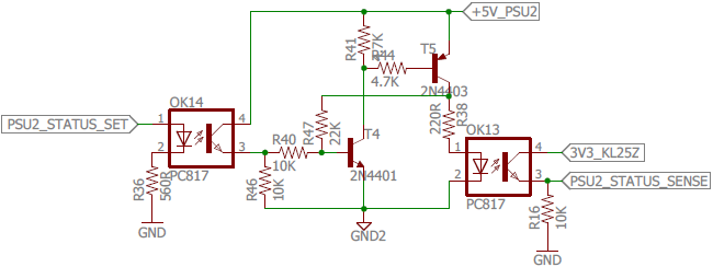
"Connect GND to a Ground pin on the KL25Z (see KL25Z Pin Out)

  • Connect 3V3_KL25Z to a 3.3V pin on the KL25Z (see KL25Z Pin Out)
  • Connect GND2 to the secondary power supply ground (the one plugged into the switched outlet)
  • Connect +5V_PSU2 to the secondary power supply +5V
  • Connect PSU2_STATUS_SENSE to the KL25Z GPIO port assigned as "Power status input" in the Pinscape Config Tool settings
  • Connect PSU2_STATUS_SET to the KL25Z GPIO port assigned as "Status latch output" in the Settings"

So I got to wire up the points marked in bolt?

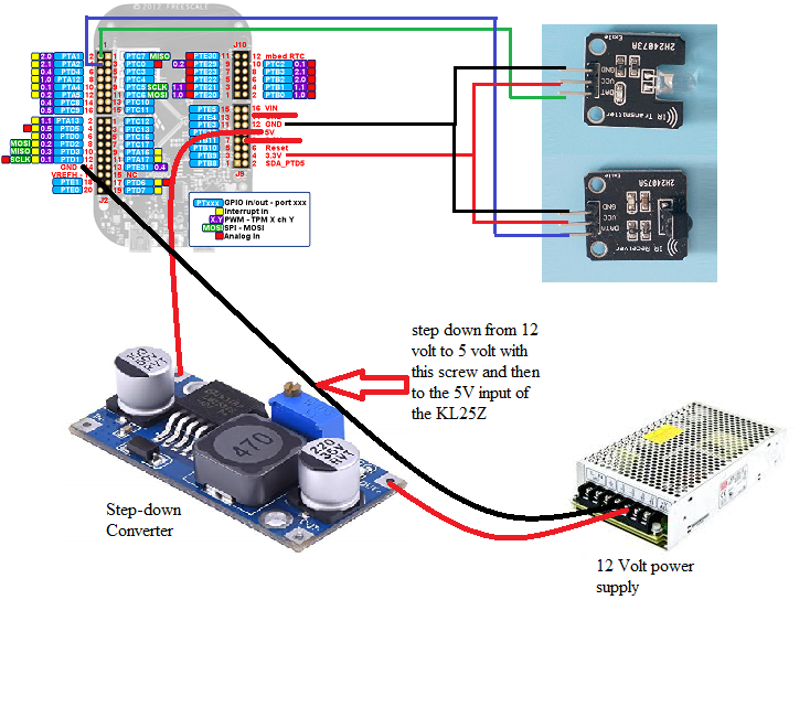
I´ve got only a 12v and 24v secondary power supply, or can i take the red 5v cable from a "Molex 8981 connector"?


#42 flstclasic

flstclasic

    Enthusiast

  • Members
  • PipPipPip
  • 182 posts

  • Flag: United States of America

  • Favorite Pinball: Attack from mars

Posted 22 July 2019 - 06:56 AM

http://mjrnet.org/pi...ide.php?sid=toc

Go to the bottom of the guide (number 99) TV ON Switch.

#43 Luckysprite

Luckysprite

    Hobbyist

  • Members
  • PipPip
  • 23 posts

  • Flag: Germany

  • Favorite Pinball: Fun House

Posted 23 July 2019 - 10:08 AM

Is it possible to use my 12 Volt power supply with an step down converter and then wire it to the 5V input on the KL25Z?

And the GND2 directly to the 12 Volt supply?


Would this be ok for the power sensing curcuit?


#44 mjr

mjr

    Pinball Wizard

  • Members
  • PipPipPipPipPip
  • 3,278 posts

  • Flag: United States of America

  • Favorite Pinball: Medieval Madness

Posted 23 July 2019 - 05:20 PM

Is it possible to use my 12 Volt power supply with an step down converter and then wire it to the 5V input on the KL25Z?

And the GND2 directly to the 12 Volt supply?


Would this be ok for the power sensing curcuit?


Just to be sure we're talking about the same thing, you read this section:


http://mjrnet.org/pi...de.php?sid=tvon


and specifically the portion that starts with the heading "Power sensing circuit", right?  So we're talking about this circuit, right?


PSU2PowerSense.png


I just want to make sure you didn't think that's part of the KL25Z somehow.  It's not - those are all external parts that you have to add on to build the power sensor.


As long as you've built all of that, then yes, you could use a 12V power supply with a 5V regulator to produce the +5V_PSU2 voltage, and use the (-) or 0V side of the regulator output as GND2.


#45 Luckysprite

Luckysprite

    Hobbyist

  • Members
  • PipPip
  • 23 posts

  • Flag: Germany

  • Favorite Pinball: Fun House

Posted 24 July 2019 - 01:24 PM

9t9jmmus.png

"A Picture is worth a thousand words" a german Phrase :dblthumb: 

​The power sensing circuit is part of the expansion board which I don´t have, I Only got the KL25Z.


Now I want to wire it up like it´s shown in the picture, will this work for me.

I hope that I have build up all circuits corresponding to your circuit diagram, I´m not an electrician so I´m not able to read those diagrams  :hmm: 


#46 mjr

mjr

    Pinball Wizard

  • Members
  • PipPipPipPipPip
  • 3,278 posts

  • Flag: United States of America

  • Favorite Pinball: Medieval Madness

Posted 24 July 2019 - 05:09 PM

9t9jmmus.png

​The power sensing circuit is part of the expansion board which I don´t have, I Only got the KL25Z.


It might be easier to try a Windows startup task instead, then.  You can use the PinscapeCmd.exe program (it's installed in the same folder as the config tool) to send IR commands from Windows batch scripts:


C:\path_to\PinscapeCmd.exe  SendIR=3


That triggers IR command #3 (as listed in the config tool's list of programmed commands) on the IR transmitter.  Change the "3" to whichever command number you used to program the "ON" button for the TV.  Put that in a .BAT file and set up the .BAT file to run as a startup task, which you can do using Windows Task Scheduler or more simply by putting it in the Startup folder in your Start Menu.


#47 Luckysprite

Luckysprite

    Hobbyist

  • Members
  • PipPip
  • 23 posts

  • Flag: Germany

  • Favorite Pinball: Fun House

Posted 25 July 2019 - 07:23 AM

I will try this later at home with the cmd.exe, seems to be the easiest option.


But the other option would work too, or? I can´t even see my uploaded picture  :shutup1: 


#48 mjr

mjr

    Pinball Wizard

  • Members
  • PipPipPipPipPip
  • 3,278 posts

  • Flag: United States of America

  • Favorite Pinball: Medieval Madness

Posted 25 July 2019 - 05:04 PM

I will try this later at home with the cmd.exe, seems to be the easiest option.

But the other option would work too, or? 


By "the other option" you mean the power-sensing circuit?  That'll certainly work; it's just more effort, especially since you said you're not too comfortable with reading schematics.


#49 Luckysprite

Luckysprite

    Hobbyist

  • Members
  • PipPip
  • 23 posts

  • Flag: Germany

  • Favorite Pinball: Fun House

Posted 29 July 2019 - 06:12 AM

Good morning mjr,


your solution is working fine with the cmd.exe, wrote a simple batch data and put it into the autostart and it works  :love39:  ​ thank you.


#50 Luckysprite

Luckysprite

    Hobbyist

  • Members
  • PipPip
  • 23 posts

  • Flag: Germany

  • Favorite Pinball: Fun House

Posted 29 July 2019 - 08:57 AM

.


Edited by Luckysprite, 29 July 2019 - 11:55 AM.


#51 coreduo0099

coreduo0099

    Enthusiast

  • Members
  • PipPipPip
  • 109 posts

  • Flag: United States of America

  • Favorite Pinball: Tommy

Posted 17 August 2019 - 03:23 AM

Anyone have a parts list or pic of their power sensing circuit?  Also, what are the two sense lines?  I don't see those on my PS.  could they just be 3.3v and ground?


#52 flstclasic

flstclasic

    Enthusiast

  • Members
  • PipPipPip
  • 182 posts

  • Flag: United States of America

  • Favorite Pinball: Attack from mars

Posted 17 August 2019 - 04:52 AM

http://mjrnet.org/pi...ide.php?sid=toc

Chapter 77. Electronic parts list.
http://mjrnet.org/pi...2PowerSense.png

#53 coreduo0099

coreduo0099

    Enthusiast

  • Members
  • PipPipPip
  • 109 posts

  • Flag: United States of America

  • Favorite Pinball: Tommy

Posted 24 August 2019 - 04:54 PM

Thanks, my questions were based on me reading that section of the site repeatedly. 


I guess I'm looking for final pictures and mouser like parts list vs schematics.  I'm not an EE but have build lots of custom parts for my cab so far.


#54 mjr

mjr

    Pinball Wizard

  • Members
  • PipPipPipPipPip
  • 3,278 posts

  • Flag: United States of America

  • Favorite Pinball: Medieval Madness

Posted 24 August 2019 - 05:45 PM

Anyone have a parts list or pic of their power sensing circuit?  


The parts are all shown in the schematic - everything is pretty generic.  "PC817" is a particular kind of optocoupler that you can search for with that part number.  "2N4401" and "2N4403" are likewise particular transistor part numbers.  Everything else is a resistor; those are completely generic and just need to match the "ohms" values shown.


Also, what are the two sense lines?  I don't see those on my PS.  could they just be 3.3v and ground?


No, those are outputs from the circuit that have to be connected to the KL25Z, as listed in that bullet list right under the schematic ("connect PSU2_STATUS_SENSE to...").


#55 Cadorna

Cadorna

    Enthusiast

  • Members
  • PipPipPip
  • 134 posts

  • Flag: Argentina

  • Favorite Pinball: Too many to choose ...

Posted 30 December 2020 - 02:25 AM

Hi mjr.
 
So, could I replace all the IR parts with the following solution? Electronically seems to be probable, but I don't know what so long is the signal sent from the KL25Z and if I should do any other change...any advice please?


https://1drv.ms/u/s!...2EiVJqDs-qvymVw


Edited by Cadorna, 30 December 2020 - 03:15 AM.


#56 mjr

mjr

    Pinball Wizard

  • Members
  • PipPipPipPipPip
  • 3,278 posts

  • Flag: United States of America

  • Favorite Pinball: Medieval Madness

Posted 30 December 2020 - 09:02 PM

So, could I replace all the IR parts with the following solution? Electronically seems to be probable, but I don't know what so long is the signal sent from the KL25Z and if I should do any other change...any advice please?


https://1drv.ms/u/s!...2EiVJqDs-qvymVw


If you want to do it that way, ignore the IR stuff and look at Connecting a hard-wired TV ON switch here:


http://mjrnet.org/pi...de.php?sid=tvon


You have basically the right idea, it's just that there's no need to get any of the IR software/hardware pathway involved, since hard-wired switches like you want to do are specifically supported in the software.


#57 Cadorna

Cadorna

    Enthusiast

  • Members
  • PipPipPip
  • 134 posts

  • Flag: Argentina

  • Favorite Pinball: Too many to choose ...

Posted 30 December 2020 - 09:17 PM


So, could I replace all the IR parts with the following solution? Electronically seems to be probable, but I don't know what so long is the signal sent from the KL25Z and if I should do any other change...any advice please?


https://1drv.ms/u/s!...2EiVJqDs-qvymVw


If you want to do it that way, ignore the IR stuff and look at Connecting a hard-wired TV ON switch here:


http://mjrnet.org/pi...de.php?sid=tvon


You have basically the right idea, it's just that there's no need to get any of the IR software/hardware pathway involved, since hard-wired switches like you want to do are specifically supported in the software.


Thanks for the link, I found that interesting:
 

How it works
The TV ON feature works by having the Pinscape software send a "Power On" command to the TV a short time after the computer turns on. To physically send the command to the TV, there are two possibilities:
  • By wires soldered to the switch terminals of the ON button on the TV itself. We connect these wires to a relay controlled by the Pinscape device. The Pinscape software pulses the relay shortly after the computer turns on. The TV registers this as an ON button press.


So, may I connect a relay DIRECTLY to the KL25Z without a transistor ? Am I right? 


#58 mjr

mjr

    Pinball Wizard

  • Members
  • PipPipPipPipPip
  • 3,278 posts

  • Flag: United States of America

  • Favorite Pinball: Medieval Madness

Posted 30 December 2020 - 09:27 PM

So, may I connect a relay DIRECTLY to the KL25Z without a transistor ? Am I right? 


No, definitely not!  You had the right idea with the transistor booster circuit.  Go back and read the section on wiring under Standalone wiring (no expansion boards).


#59 Cadorna

Cadorna

    Enthusiast

  • Members
  • PipPipPip
  • 134 posts

  • Flag: Argentina

  • Favorite Pinball: Too many to choose ...

Posted 30 December 2020 - 09:43 PM


So, may I connect a relay DIRECTLY to the KL25Z without a transistor ? Am I right? 


No, definitely not!  You had the right idea with the transistor booster circuit.  Go back and read the section on wiring under Standalone wiring (no expansion boards).


Thanks again, now I see it. That solution uses a photocoupler I assume is for extra protection for the KL25Z, good idea I'll put into practice! 


#60 Cadorna

Cadorna

    Enthusiast

  • Members
  • PipPipPip
  • 134 posts

  • Flag: Argentina

  • Favorite Pinball: Too many to choose ...

Posted 12 January 2021 - 11:09 PM

Hi there.


These both modules, transmitter, and receiver, also works fine with the KL25Z board.
 
Just take note that they must to be connected to 5 volts, not 3.3v.
 

https://1drv.ms/u/s!...Hq3FaQ?e=sEKRYv


Regards.