Jump to content


Photo
* * * * * 7 votes

Pinscape expansion board support thread


  • Please log in to reply
1071 replies to this topic

#1 mjr

mjr

    Pinball Wizard

  • Members
  • PipPipPipPipPip
  • 3,069 posts

  • Flag: United States of America

  • Favorite Pinball: Medieval Madness

Posted 01 March 2016 - 06:35 PM

It looks like my original attempt at this thread got lost in a site crash, so I'll try again.  Hopefully this one will survive a little longer...


The Pinscape boards from the first group order are here!  But the documentation isn't.  So I'm starting this thread as a place for Q&A to help people out until real documentation is ready.  If you have any questions about how to proceed with building the boards, post them here and I'll try to answer them promptly.  (I could also answer questions by email, but I'd rather use the public forum thread so that everyone can benefit from the discussion.)


See http://www.vpforums....showtopic=32700 and http://mjrnet.org/pinscape/expansion-board.html for more information on the boards themselves.


Edited by mjr, 01 March 2016 - 06:36 PM.


#2 roar

roar

    Enthusiast

  • Members
  • PipPipPip
  • 452 posts

  • Flag: Canada

  • Favorite Pinball: TOM

Posted 05 March 2016 - 05:14 AM

Got all my parts in today... probably try and solder some down tomorrow... focusing on the Interface Board and Power Board first, Chime can come another time.


Trying to work from the image you have over at mjrnet.org when placing my components and I'm making the assumption the writing on the chips should match the writing on the board from an orientation perspective as I don't see any indications on the chips themselves which leg may be the first one. Some of these solder points are really tight... like the ones next to IC1 and IC2 C1 and C4 respectively, this will test my very rudimentary soldering skills :)


Not sure if I missed this somewhere, but I do seem to have the headers(not sure if that is the right term) to connect the power board to the interface board, but the part list doesn't appear to include the cable to go between the two. Am I mistaken?


Edited by roar, 05 March 2016 - 05:23 AM.


#3 mjr

mjr

    Pinball Wizard

  • Members
  • PipPipPipPipPip
  • 3,069 posts

  • Flag: United States of America

  • Favorite Pinball: Medieval Madness

Posted 05 March 2016 - 06:17 AM


Trying to work from the image you have over at mjrnet.org when placing my components and I'm making the assumption the writing on the chips should match the writing on the board from an orientation perspective as I don't see any indications on the chips themselves which leg may be the first one. 


Definitely be careful about the orientation.  And beware of relying too much on those pics - a couple of chips got reversed between the "beta" boards (in the pictures) and the final rev, mostly to make everything more consistent.


There are basically two ways that they identify pin 1 on the IC packaging.  


- A little half-moon notch on one side.  That's how everything is depicted on the outlines on the board.  If you can spot the notch, line it up with the one on the board outline and you're golden.  In this case, put the notch at the left, and the bottom left pin is pin 1.


- A small white dot in one corner.  The nearest pin is pin 1.  


In general, pin 1 is always the bottom left pin when you have it oriented properly.


Hopefully this diagram will help:


icpin1finder.png


Note that the notches and dots are sometimes pretty subtle, so you might need to get out your magnifying glass.  They're sometimes just little indents.


Some of these solder points are really tight... like the ones next to IC1 and IC2 C1 and C4 respectively, this will test my very rudimentary soldering skills  :)


C1 and C4 are kind of special cases that are supposed to be really tight - the chips need these to be jammed right up against the pins with as little wire as possible.  So it's not quite as tricky to solder as it looks, because they're actually connected to the pins they're so close to.


And because the chips want the close connection to C1 and C4, it's best to get the body of the capacitor as close to the board as you can with minimal lead wire length.  That's good to do in general, but it's especially worthwhile for these.


Not sure if I missed this somewhere, but I do seem to have the headers(not sure if that is the right term) to connect the power board to the interface board, but the part list doesn't appear to include the cable to go between the two. Am I mistaken?


A pair of IDC housings for the connector cable are in the power board parts list, but I don't think I added anything for the ribbon cable itself, since that's usually sold by the foot and you'll want to pick the length you need.  Likewise, the chime board has a pair of housings for its connector.  I figured that the cable belongs with the daughter board, which is why I grouped the parts lists that way.


You can also probably just buy a preassembled ribbon cable with connectors on each end on eBay if you look around.  I'll put together some notes on how to assemble the IDC cable if you want to do it yourself - it's really easy once you have the parts.


Edited by mjr, 05 March 2016 - 06:34 AM.


#4 roar

roar

    Enthusiast

  • Members
  • PipPipPip
  • 452 posts

  • Flag: Canada

  • Favorite Pinball: TOM

Posted 06 March 2016 - 04:44 AM

Thanks for all that mjr... I still managed to screw up one of my chips, lots of fun pulling that out. It ain't pretty but it is moving along. I've got most of the headers and chips in place moving on to resistors, with a giant back of little bags this can be like finding a needle in a haystack... but on the resistor front... are those directional as well? Google tells me they aren't but I thought I should check in before soldering a pile of these things :)


Edit: I should have asked the same about the capacitors, the 1uF's have their positive hole marked, but the ones for C6, C4 and C1 for example do not.


Edited by roar, 06 March 2016 - 04:49 AM.


#5 Slydog43

Slydog43

    Pinball Wizard

  • Platinum Supporter
  • 3,006 posts
  • Location:Hackettstown, NJ

  • Flag: United States of America

  • Favorite Pinball: Addams Family, All Williams 90's Games

Posted 06 March 2016 - 12:43 PM

sorry, but can't remember if I paid for the few boards that I wanted.  If I haven't how do I pay and how much?  thanks  Steve


#6 mjr

mjr

    Pinball Wizard

  • Members
  • PipPipPipPipPip
  • 3,069 posts

  • Flag: United States of America

  • Favorite Pinball: Medieval Madness

Posted 07 March 2016 - 05:02 AM

Thanks for all that mjr... I still managed to screw up one of my chips, lots of fun pulling that out.


I know what that's like. :(  Glad you were able to get it out.


I've got most of the headers and chips in place moving on to resistors, with a giant back of little bags this can be like finding a needle in a haystack... but on the resistor front... are those directional as well? 


Yeah, there are lots of parts to keep track of - it at least goes a long way that Mouser packages them up so nicely.  My strategy when soldering is to group all of the resistor baggies together on the table in front of me and sort them by resistance value, which makes it fairly quick to find the right one each time.


And in answer to your real question here:  Resistors are always non-directional - you can install them either way and they'll work exactly the same.


Edit: I should have asked the same about the capacitors, the 1uF's have their positive hole marked, but the ones for C6, C4 and C1 for example do not.


In general, there are two kinds of capacitors:  electrolytic and ceramic.  


The electrolytics are the ones in the cylindrical metal cases.  These are always polarized, so the direction matters.  The packaging usually has two features that tell you which leg is (+) and which is (-).  First, one wire is usually visibly longer than the other - that's the positive.  Second, the case usually has an arrow or stripe down one side with "- - -" (repeated minus signs).  The stripe marks the negative leg.  On the smaller packages like the 1uF capacitors, that can be hard to spot, but it's almost always there.


The ceramic capacitors are the much smaller ones that usually look like either flat disks or little plastic nodules.  These are NOT polarized, so it doesn't matter which way they go (just like resistors).


If you see a "+" sign printed on the circuit board for a particular capacitor, that capacitor should be an electrolytic, so do pay attention to orientation.  If you don't see a "+" sign in the outline, that SHOULD mean the capacitor that goes there is a non-polarized ceramic.  If the part you're about to install doesn't match up with that rule, definitely double-check that you grabbed the right part, and if it still doesn't look right, shoot me a note so we can confer and make sure the marking isn't screwed up on the board.  EAGLE makes it pretty hard to screw those up because the "+" marking is part of the standard capacitor symbols it provides, but I could still have picked the wrong part, so if you catch anything that doesn't add up after looking closely, you might well have caught a mistake on my part!


I just double-checked C1, C4, and C6, and they are indeed all non-polarized ceramics, so those can go either direction.


sorry, but can't remember if I paid for the few boards that I wanted.  If I haven't how do I pay and how much?  thanks  Steve


Hi, Steve!  I do have you on my reservation list, but I haven't heard from you yet to get payment and shipping details, so drop me a note when you have a chance at [email protected].


Apologies for not reaching out via PM - the mailbox quota restrictions here make that pretty unworkable, so I've hoping everyone will see the announcements on the threads so we can make contact by regular email.


#7 roar

roar

    Enthusiast

  • Members
  • PipPipPip
  • 452 posts

  • Flag: Canada

  • Favorite Pinball: TOM

Posted 12 March 2016 - 01:58 PM

mjr... I've made some progress and I've got what I believe to be most of the components on the board. There are a couple though I could use a hand with before I commit.


R11, the board says a 27R, I've got a 270hm resistor, but no 27, I'm guessing the 270 goes there?


Next up is the R2 4K. I've got two 4.02ohms, one is P/N ending in KR36 the other is 21F2, not sure which one should fit there, or if I should have a 4K one somewhere and I may have put that in the wrong place?


Next up is D1, No idea what part that is :)


Next up U$2, board is calling for a TSOP 


Next up IC12, not clear to me what's going in there


Last but not least, Q1.


I clearly should have wait for your directions, as I am sure these questions will be answered there, I do thank you for all your support!


#8 mjr

mjr

    Pinball Wizard

  • Members
  • PipPipPipPipPip
  • 3,069 posts

  • Flag: United States of America

  • Favorite Pinball: Medieval Madness

Posted 12 March 2016 - 06:34 PM

mjr... I've made some progress and I've got what I believe to be most of the components on the board. There are a couple though I could use a hand with before I commit.


Glad you're making such good progress!


R11, the board says a 27R, I've got a 270hm resistor, but no 27, I'm guessing the 270 goes there?

Next up U$2, board is calling for a TSOP 

 
Both of those parts are for the TV IR remote transmitter/receiver subsystem.  That was a late addition, so if you ordered the parts before the very last rev of the Mouser cart, those weren't in there.  You can just leave those slots empty if you didn't get the parts and don't need the IR remote features.  And even if you leave them empty now, you can go back and add them at any time in the future.
 
You actually do want a 27 ohm resistor for R11, not 270.  But this one varies according to what you're going to use for IR LEDs.  If you have the schematic handy, there are some notes at the bottom of page 4 about the resistor choice.  The reason it varies is that this resistor is simply the current-limiting resistor for the IR LEDs, so the size depends on which LEDs you choose and how many of them you're using.  If you're not going to attach any IR transmitter LEDs, you can just leave this empty.
 
U$2 is the IR receiver sensor, which looks like an LED with three legs instead of two.  That "TSOP" you see is referring to the part number on this, TSOP38238.  Again, if you didn't order one and don't need the IR feature, just leave this empty.


Next up is the R2 4K. I've got two 4.02ohms, one is P/N ending in KR36 the other is 21F2, not sure which one should fit there, or if I should have a 4K one somewhere and I may have put that in the wrong place?

 
Hopefully the 4.02ohm you have is actually a 4.02 K ohm - that's what I *should* have put on the parts list.  The 4.02K is the closest I could find to 4K, so I went with that in the parts list even though the marked size a tiny bit different.  (Electrically, 4K was the size needed, but that's not a standard manufactured size, so I had to approximate.  The slight different is negligible electrically in this case.)
 
Double-check that the "4.02" part you have is actually a 4.02 K, and assuming it is, that's the one to use here.


Next up is D1, No idea what part that is  :)

 
That's a diode - there should have been a 1N4007 diode in the parts list.
 
Note that diodes are polarized, so you have to install this in the right direction.  In the outline marking on the circuit board, you should see a little arrow pointing at a thick stripe at one end.  On the diode itself, you should also be able to see a white stripe on one end.  Just line up the stripe on the diode with the stripe on the circuit board.


Next up IC12, not clear to me what's going in there

 
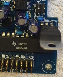
That's the little voltage regulator chip - the part number on the Mouser bag is LD1117AV33.  (That's marked on the board as well, but the name is so long that the text is practically microscopic.)   It looks exactly like a MOSFET - it uses the exact same device package, the black plastic square with three legs and a big heat sink on the back.  Like the MOSFETs, line this up on the board so that the package is oriented like the outline on the board.  The outline on the board is meant to look like the package when viewed from above - hopefully it's intuitively clear what's intended from the way they draw it.


Last but not least, Q1.

 
That's the MOSFET.  If you got the MOSFET from Mouser, I think the part number you should have is FQP30N06L (or maybe FQP13N06L).  Physically, this device looks exactly like the voltage regular chip above.  It has the same kind of outline on the board showing how to orient it.
 
This MOSFET is the replay knocker power driver, by the way.  It's the big power transistor that switches the knocker solenoid power on and off when DOF sends the appropriate commands to the KL25Z.


I clearly should have wait for your directions, as I am sure these questions will be answered there, I do thank you for all your support!

 
Selfishly, I'm actually kind of glad you've gotten ahead of me on the doc here - it's really helpful to know which areas need the extra explanation.
 

I'm *still* plugging away at the software update, so I'm not quite ready to start the doc yet.  I was hoping to be done with the new software by the end of this past week, but as always there was more work than I anticipated.  I think I'm finally in the home stretch on it, though - I'm hoping (again) that one more week will be enough to get the first beta rev out.


Edited by mjr, 12 March 2016 - 06:35 PM.


#9 roar

roar

    Enthusiast

  • Members
  • PipPipPip
  • 452 posts

  • Flag: Canada

  • Favorite Pinball: TOM

Posted 12 March 2016 - 11:58 PM

i'm relieved to hear that I am not too big of a pain.


It does look like I have the TV parts... for the exception of the 27R, I'll read the schematics and consider looking at that another time. All 3 legs on the TSOP are the same length and I don't see any indication of direction on the board so I'm going point the curved side away from the board.


On the 4.02K Resistor front, both do say 4.02K. One says 1/3watt 4.02Kohms 1% and the other says 4.02Kohms 1% 100PPM, so not sure which one to use.


I think I've got the orientation of the MOFSET and voltage regulator chip right, but I've post a picture to be sure. I've also cropped out as much as I could as to not have my soldering skills judged :)


25108506754_ed015cac86.jpg


#10 mjr

mjr

    Pinball Wizard

  • Members
  • PipPipPipPipPip
  • 3,069 posts

  • Flag: United States of America

  • Favorite Pinball: Medieval Madness

Posted 13 March 2016 - 12:42 AM

i'm relieved to hear that I am not too big of a pain.

 
Not at all!  These are all good questions.


All 3 legs on the TSOP are the same length and I don't see any indication of direction on the board so I'm going point the curved side away from the board.

 
That is correct.  I just realized that the marking is fairly easy to see on the EAGLE board diagram, but not on the board itself - it hangs over the edge of the board in such a way that the important bit got cut off.  Sorry about that!  The curved part does face outwards. 
 
Also note that this part might be too tall to fit under the KL25Z comfortably when standing straight up.  I'm not sure yet, but I was thinking of installing it with a little extra leg wire sticking up, and then bending the legs 90 degrees so that the whole thing is hanging out over the edge of the board and facing down.  Does that make any sense?  I haven't drawn up a diagram of that yet, so I hope you get what I mean from the description.  If not let me know and I'll try to draw a picture.
 
On the other hand, it might just fit standing up, in which case that angling won't be necessary.  I just haven't built that part yet so I'm not certain.


On the 4.02K Resistor front, both do say 4.02K. One says 1/3watt 4.02Kohms 1% and the other says 4.02Kohms 1% 100PPM, so not sure which one to use.

 
I'll have to look at the parts list and see why there are the two kinds - that might have been an oversight on my part.  For R2, you don't need any big wattage, so either one will work.  If one is physically smaller I'd plug that one for that slot.


I think I've got the orientation of the MOFSET and voltage regulator chip right, but I've post a picture to be sure. I've also cropped out as much as I could as to not have my soldering skills judged  :)


25108506754_ed015cac86.jpg


That looks right!  You can't tell from this photo, but for anyone else reading this who wants a way to double-check, the thick line printed on the board in the MOSFET/IC footprint represents the metal fin on the back of the MOSFET/IC.  You just line up the metal fin side on the actual part with the picture on the board.


#11 roar

roar

    Enthusiast

  • Members
  • PipPipPip
  • 452 posts

  • Flag: Canada

  • Favorite Pinball: TOM

Posted 13 March 2016 - 01:09 AM

Plugging my soldering iron back in!


Next up... questions on the KL25Z, I've put a set of 16 pins down on the main board for the first 16 pins on KL25Z, but there was not set of 20 pins for the next bank. Do only need to use the 16 pins to attach to the KL25Z?


#12 mjr

mjr

    Pinball Wizard

  • Members
  • PipPipPipPipPip
  • 3,069 posts

  • Flag: United States of America

  • Favorite Pinball: Medieval Madness

Posted 13 March 2016 - 01:18 AM

Next up... questions on the KL25Z, I've put a set of 16 pins down on the main board for the first 16 pins on KL25Z, but there was not set of 20 pins for the next bank. Do only need to use the 16 pins to attach to the KL25Z?


You do need to connect them all - I'll have to check the parts list and see why you don't have a 10+10.  


Note that you can install the KL25Z sockets and pins two different ways:


- Pin headers on the top of the expansion board, matching sockets on the BOTTOM of the KL25Z with the openings facing down


- Sockets on the top of the expansion board, pin headers on the BOTTOM of the KL25Z with the pins pointing down


I did the latter, but either way should work.  If you're putting the sockets on the KL25Z side, just make sure they're on the bottom side so that it mates up correctly - you should be able to see from the board which way that is since the groupings aren't symmetrical (it forms a natural "key" that makes sure you get it in the right way).  You *might* have to un-stick the little rubber feet on the bottom of the KL25Z to make room.  They're not very aggressively attached - it seems to be basically rubber cement holding them on - so they're fairly easy to peel off and stick back on a couple of millimeters over, out of the way.  You don't actually even need to keep the rubber feet at all since the sockets/pins will serve as all the support the thing needs.


#13 roar

roar

    Enthusiast

  • Members
  • PipPipPip
  • 452 posts

  • Flag: Canada

  • Favorite Pinball: TOM

Posted 13 March 2016 - 01:50 AM

Thanks mjr... I believe I have taken this as far as I can go for now. I seem to be missing a 10+10 set of pins and a 6+6 socket. I've got a place local to me that sells components like these, but I'm doubtful they will have a 6+6 socket. I'm confident I can cut down a set of pins if they are greater than 10+10, but I may need to order a 6+6. I did as you had suggested with the IR receiver and bent it 90 degrees it would not have fit otherwise I don't think.

Edited by roar, 13 March 2016 - 02:09 AM.


#14 NobodyYouKnow

NobodyYouKnow

    Hobbyist

  • Platinum Supporter
  • 48 posts

  • Flag: United States of America

  • Favorite Pinball: Space Invaders

Posted 13 March 2016 - 04:00 AM

Hey Mike. I have recently finished the PinScape expansion board build. Thus far, I have verified all the Key(n)  inputs work and that the TV power control relay works. Next I will breadboard in some low power LEDs and a few RGB LEDs and check those outputs. This is looking pretty good. Nice work!


Is there a test utility out there for these boards? I would like to arbitrarily turn on LEDs and MOSFET outputs to test them. I have been using the Windows 7 "Game Controller" console snap-in to look at button inputs and board nudge. It's utility ends about there. I suspect some of the LEDWiz tools will work, but figured I'd be smart to ask first - I'd hate to fry something just because I did not know what I was doing.


Note to readers - be sure to follow the instructions in the build manual regarding changing the PinScape "config.h" file. I spent a couple of hours trying to find a board construction fault, when it was software all along. If you see Key6 stuck on when the KL25Z is attached to the expansion board, this will fix it. Read through the "Customize the controller software" section on page 6. Pay attention to the line in "config.h" that looks like "// #define EXPANSION_BOARD". Just delete the "//" and recompile. It works like a champ, and the "config.h" file is very well documented.


Regards.


Edited by NobodyYouKnow, 13 March 2016 - 04:47 AM.


#15 NobodyYouKnow

NobodyYouKnow

    Hobbyist

  • Platinum Supporter
  • 48 posts

  • Flag: United States of America

  • Favorite Pinball: Space Invaders

Posted 13 March 2016 - 07:02 PM

I am having a bit of trouble getting what I think is proper LED output from the expansion board, I do not yet have a cabinet built, so I am using LEDBlinky as a test platform. I want to ensure I understand the path from the expansion board hardware, all the way up to LEDBlinky. I can get proper LED output states using the bare KL25Z. Once I add the expansion board and re-configured PinScape software, everything gets weird.


Can you provide guidance for a simple test setup for evaluating a single LED output channel? I do not mind going a different direction than LEDBlinky. It just looks like a good low complexity test fixture.


I am looking through the PinScape "config.h" file and am finding a reference in a comment I do not understand. Beginning at line 720 (or so) I see the following:


    { PTA1,  PWM_GPIO },      // pin J1-2,  LW port 1  (PWM capable - TPM 2.0 = channel 9)
    { PTA2,  PWM_GPIO },      // pin J1-4,  LW port 2  (PWM capable - TPM 2.1 = channel 10)

    . . .
 

What is "TPM" and how does it relate to both the PinScape software / hardware? How does it relate to LEDWiz?


Thank you!


(edit) I got a little smarter. The above line 720 excerpt applies only if there are no TLC-5940's present. For me this is true when I am running a bare KL25Z board with "EXPANSION_BOARD" not #DEFINEd (and consequently "TLC5940_NCHIPS ==0"). I still do not know what the acronym TPM is about. This is nearly moot, since PinScape on the bare KL25Z works perfectly.


Edited by NobodyYouKnow, 14 March 2016 - 02:05 AM.


#16 mjr

mjr

    Pinball Wizard

  • Members
  • PipPipPipPipPip
  • 3,069 posts

  • Flag: United States of America

  • Favorite Pinball: Medieval Madness

Posted 13 March 2016 - 07:13 PM

Hey Mike. I have recently finished the PinScape expansion board build. Thus far, I have verified all the Key(n)  inputs work and that the TV power control relay works. Next I will breadboard in some low power LEDs and a few RGB LEDs and check those outputs. This is looking pretty good. Nice work!


That's great to hear!


Is there a test utility out there for these boards? I would like to arbitrarily turn on LEDs and MOSFET outputs to test them. I have been using the Windows 7 "Game Controller" console snap-in to look at button inputs and board nudge. It's utility ends about there. I suspect some of the LEDWiz tools will work, but figured I'd be smart to ask first - I'd hate to fry something just because I did not know what I was doing.


I've been using an embarrassingly crude tool that I cobbled together.  It's on the website here:


http://mjrnet.org/pinscape/index.html


Scroll down to the bottom - last entry is "DOF R3 Setup Tester".  That's a little DOS command-line tool that lets you control individual outputs.  There's a readme file explaining how to use it.  I'm going to try to put an easier-to-use tester in the config tool, but I'm still working on that, so hopefully this will help in the meantime.  Note that you'll need DOF R3 installed to use this program.


You also certainly can use any tool that can control an LedWiz as well.  The controller software provides a full LedWiz emulation, so it works with any PC software that works with an LedWiz.  Note, though, that the unit numbering can be a snag for some software.  Most LedWiz clients on the PC are hard-wired to use unit #1 with no option to control different unit numbers (DOF is the rare exception).  Fortunately, there's an easy solution - just edit config.h and set the LedWiz unit number to 1.  Also, the LedWiz protocol is inherently limited to 32 ports, so an LedWiz client will only be able to control ports 1-32.  To take advantage of the expanded port set, you have to use the extended protocol, which DOF R3 speaks, but older LedWiz clients don't.


#17 roar

roar

    Enthusiast

  • Members
  • PipPipPip
  • 452 posts

  • Flag: Canada

  • Favorite Pinball: TOM

Posted 16 March 2016 - 03:03 AM

Looks like I didn't make complete meal of this project... Yet :) I picked up some header pins and sockets today and finished my soldering tasks and was able to confirm all the button inputs are working. Looks like I'll need to pick up a crimped to get things setup right any advice on what to look for?

Next up is to get some power to this thing. If my plans are to get my Helio lights working in my buttons do I need to hook up both power inputs or can I just wire up the PC PSU 5v only connector? I'm sure I'll have more questions to come.

Thanks NobodyYouKnow for the heads up on updating the config.h, when I plugged it in button 6 was locked on likes you said, that was actually a relief to see!

#18 mjr

mjr

    Pinball Wizard

  • Members
  • PipPipPipPipPip
  • 3,069 posts

  • Flag: United States of America

  • Favorite Pinball: Medieval Madness

Posted 16 March 2016 - 05:51 AM

Looks like I didn't make complete meal of this project... Yet :) I picked up some header pins and sockets today and finished my soldering tasks and was able to confirm all the button inputs are working.


Excellent!


Looks like I'll need to pick up a crimped to get things setup right any advice on what to look for?


This is the tool I use:  https://www.pololu.com/product/1928/.  It works great and it's pretty reasonably priced.  ($35.  Sounds expensive for such a specialized tool, I know.  But when you look at the competition, it starts looking like a bargain.  All of the competitors seem to be pro tools priced for corporate buyers in the $200 range.)  One slight snag: they don't include any instructions, and it's far from obvious how the tool is supposed to work.  I guess they just assume that only real EE's would even know to buy such a tool.  But fortunately there are some videos on the web that demonstrate it, and once you see how it works, it's amazingly easy to get perfect crimps every time.  I had practically zero learning curve with it.


Note that you can also get away with crimping with needle-nose pliers if you have infinite patience.  If you're going that route, I'd recommend soldering the pins instead of just crimping, since it's almost impossible to get strong enough crimps without the special tool.  (That extra soldering work is the main reason it requires such patience to forego the tool.)


Next up is to get some power to this thing. If my plans are to get my Helio lights working in my buttons do I need to hook up both power inputs or can I just wire up the PC PSU 5v only connector? 


If you run those on the flipper button/small LED outputs, you can run them from the main PC PSU 5V connection - no need for the second PSU connection.  The +5V pin on the flipper button LED header just connects directly to the PC PSU 5V input.  


And by the way, for testing purposes, it's perfectly okay to wire both power inputs to the same PSU.  The purpose of the two power supply inputs is to *allow* for isolation of the power and logic circuitry if you want it, but isolation isn't required by anything in the circuit design.  For LEDs and lamps you don't really need it.   I would recommend a second power supply as soon as you start attaching anything inductive, though (solenoids, motors).


Edited by mjr, 16 March 2016 - 05:53 AM.


#19 NobodyYouKnow

NobodyYouKnow

    Hobbyist

  • Platinum Supporter
  • 48 posts

  • Flag: United States of America

  • Favorite Pinball: Space Invaders

Posted 16 March 2016 - 06:08 AM

Thanks for the pointer to the DOF Tester tool. I have been using it to successfully test both the Flipper and Small Opto outputs. Everything looks great so far, for ports 1 - 32 at least.


Can I also use this tool to test the LEDWiz ports above 32? The documentation implies that I can. I am looking for something simple to reach out and tickle the MOSFET and CHIME boards. Right now "DirectOutputTest.exe 8 33 1" reports "Output ID ## out of range (must be 1-32)" for every LEDWiz port above 32. (## is a LEDWiz port number between 33 and 64.) On the other hand, "DirectOutputTest.exe 58 33 1" exits without error. At this point, I am pretty sure I need to be using Unit 58, not unit 8. The trouble is that I am seeing no change in activity on the MOSFET board. Stay tuned - I'll figure this one out.


Be aware there is a part position swap on the Chime board, Channels 5 and 6 appear to have identical component placement. Both channels have NPN transistors - T9 and T12; and PNP transistors - T10 and T13. If you look closely at the Chime PCB, you will see T12 and T13 swapped in reference to T9 and T10. An even closer look reveals distinctly different routing between the two channels to accommodate this swap. Unfortunately, I did not catch this until I began bench testing the board. The good news is  the other 7 channels work flawlessly.


If you are using the Chime board, there are no "HC595_PORT" channels assigned to a LEDWiz channel in "config.h". For testing I made the following alterations. Basically, I reassigned LEDWiz port numbers 25-32 from their various general purpose TLC ports to HC595 ports (The // in a line makes what follows on that line a comment.). I likely will not leave them this way as I build out my cabinet - this is just for testing.


    { 1, HC595_PORT },       // HC595 port 1, LW output 25
    { 2, HC595_PORT },       // HC595 port 2, LW output 26
    { 3, HC595_PORT },       // HC595 port 3, LW output 27
    { 4, HC595_PORT },       // HC595 port 4, LW output 28
    { 5, HC595_PORT },       // HC595 port 5, LW output 29
    { 6, HC595_PORT },       // HC595 port 6, LW output 30
    { 7, HC595_PORT },       // HC595 port 7, LW output 31
    { 8, HC595_PORT },       // HC595 port 8, LW output 32
 //   { 24, TLC_PORT },        // TLC port 24, LW output 25 - Contactor 4/General purpose
 //   { 25, TLC_PORT },        // TLC port 25, LW output 26 - Contactor 5/General purpose
 //   { 26, TLC_PORT },        // TLC port 26, LW output 27 - Contactor 6/General purpose
 //   { 27, TLC_PORT },        // TLC port 27, LW output 28 - Contactor 7/General purpose
 //   { 28, TLC_PORT },        // TLC port 28, LW output 29 - Contactor 8/General purpose
 //   { 29, TLC_PORT },        // TLC port 29, LW output 30 - Contactor 9/General purpose
 //   { 30, TLC_PORT },        // TLC port 30, LW output 31 - Contactor 10/General purpose
 //   { 31, TLC_PORT },        // TLC port 31, LW output 32 - Shaker Motor/General purpose


Bottom line this far is both the Main board and most of the Chime board work perfectly (all except channel 6). The MOSFET board still needs work.


Cheers!


#20 mjr

mjr

    Pinball Wizard

  • Members
  • PipPipPipPipPip
  • 3,069 posts

  • Flag: United States of America

  • Favorite Pinball: Medieval Madness

Posted 16 March 2016 - 06:39 PM

Thanks for the pointer to the DOF Tester tool. I have been using it to successfully test both the Flipper and Small Opto outputs. Everything looks great so far, for ports 1 - 32 at least.


Can I also use this tool to test the LEDWiz ports above 32? The documentation implies that I can. I am looking for something simple to reach out and tickle the MOSFET and CHIME boards. Right now "DirectOutputTest.exe 8 33 1" reports "Output ID ## out of range (must be 1-32)" for every LEDWiz port above 32. (## is a LEDWiz port number between 33 and 64.) On the other hand, "DirectOutputTest.exe 58 33 1" exits without error. At this point, I am pretty sure I need to be using Unit 58, not unit 8. The trouble is that I am seeing no change in activity on the MOSFET board. 


The tool works for all outputs, but as you've observed, only if you use the high numbered unit - 58 in your case, rather than 8.

Here's what's going on.  DOF sees each Pinscape unit *twice* - once as an LedWiz, and once as a Pinscape controller.  The DOF unit number from 1 to 16 is always the LedWiz interface, and the unit from 51 to 66 is always the Pinscape interface.  The LedWiz protocol is inherently limited to 32 ports, so when you talk to DOF through unit 8, you can only address ports 1-32.  The Pinscape protocol lifts that limit, so you can address all ports when you go through unit 58 in DOF.


I have made some unpublished changes to the TLC5940 software, so it's possible that the problem you're seeing is in the software rather than hardware.  If you don't find something obvious with the hardware in short order, let me know and we can look at the software.  The only snag is that the latest version of the TLC5940 source file has at least one dependency on other new files in my working version, so it might take a little work to integrate the changes back in to the published version. 


One quick thing to try:  the frequency settings in the existing published version were wrong.  In TLC5940/TLC5940.h, the frequency #define should be:


#define SPI_SPEED 28000000
 
The published version is off by a factor of 10 (2.8 MHz instead of 28 MHz).  It should still work at the lower frequency, but you might want to change your copy anyway since this is what I used when I tested my v1 build of the boards.  The other frequency change I made is
 
#define GSCLKC_SPEED 350000
 
or 350kHz - I think it's 500kHz in the published version.  Again, the other figure should work, but this is the one I used for my working build.


Be aware there is a part position swap on the Chime board, Channels 5 and 6 appear to have identical component placement. Both channels have NPN transistors - T9 and T12; and PNP transistors - T10 and T13. If you look closely at the Chime PCB, you will see T12 and T13 swapped in reference to T9 and T10. An even closer look reveals distinctly different routing between the two channels to accommodate this swap. Unfortunately, I did not catch this until I began bench testing the board. The good news is  the other 7 channels work flawlessly.


Really sorry about that!  I found a bunch of similar pointless inconsistencies in the v1 prototypes that threw me for similar loops while assembling those.  That gave me a whole new appreciation for how important it is to make things as symmetrical and regular as possible.  I missed this one, though.  I'll definitely fix it in the EAGLE layout so that at least future batches will be more consistent.