Jump to content


Photo
- - - - -

RINNIG Minicab (24" Playfield) build

minicab 24

  • Please log in to reply
15 replies to this topic

#1 pilotniq

pilotniq

    Hobbyist

  • Members
  • PipPip
  • 30 posts
  • Location:Stockholm, Sweden

  • Flag: Sweden

  • Favorite Pinball: Tommy

Posted 07 April 2015 - 06:49 PM

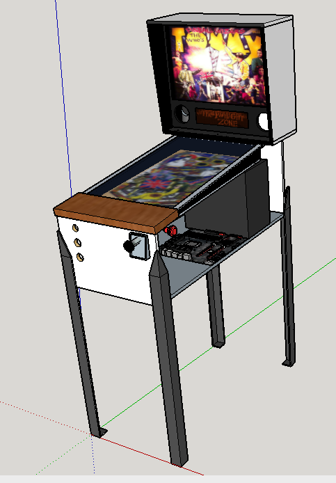
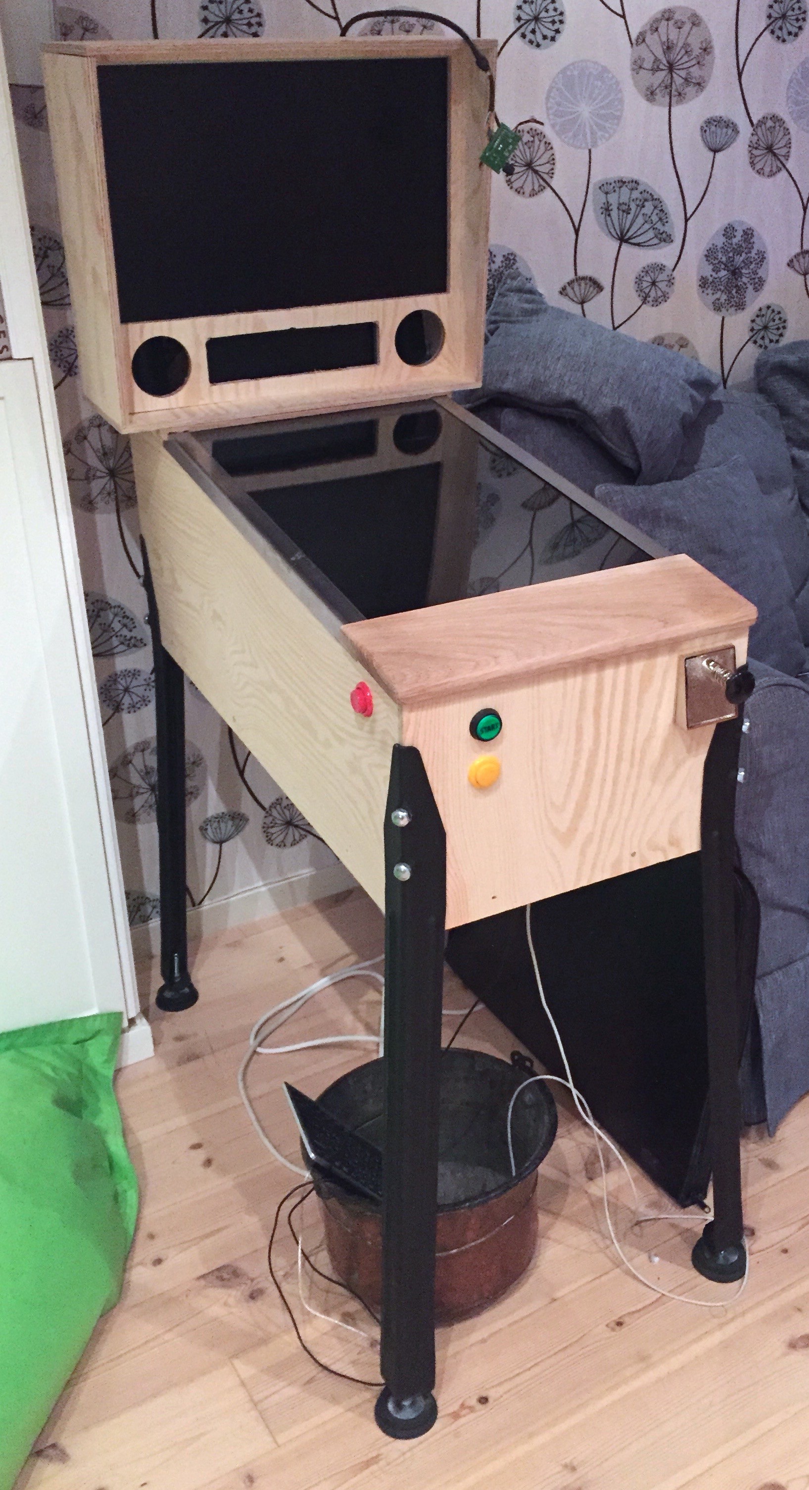
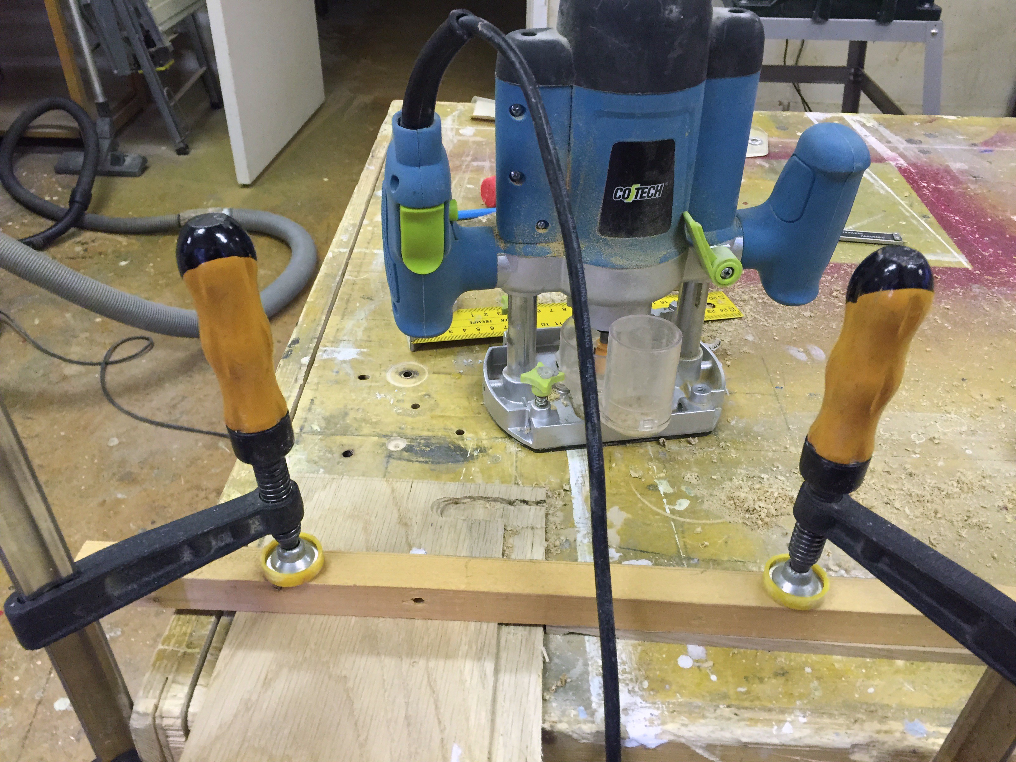
I've been building a minicab around a 24" widescreen monitor as playfield. It's at the stage of the final painting now, but I've been using most of my spare time to build rather than document it, so I have not documented it until now.


I've made a project page at Hackaday for it, but I'll cross post my log to here, in gratitude of all I've learnt from these forums.


One goal has been to make it blend in as a piece of furniture in our living room, so it will be painted glossy white on the outside.


Project Starts, Buying Monitors and Computer

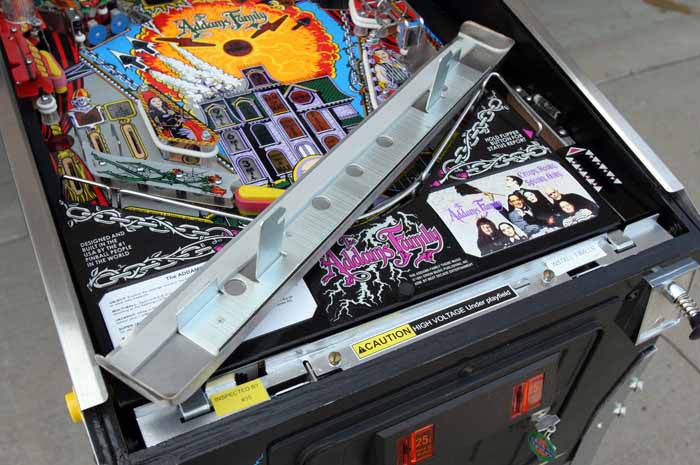
Around the beginning of December 2014, a friend of mine, Adam Klotblixt, told me about people building physical pinball cabinets with monitors as playfields, running the free Visual Pinball software. I decided this was the next project I wanted to do.

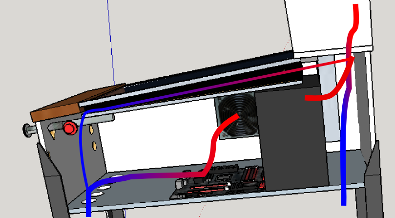
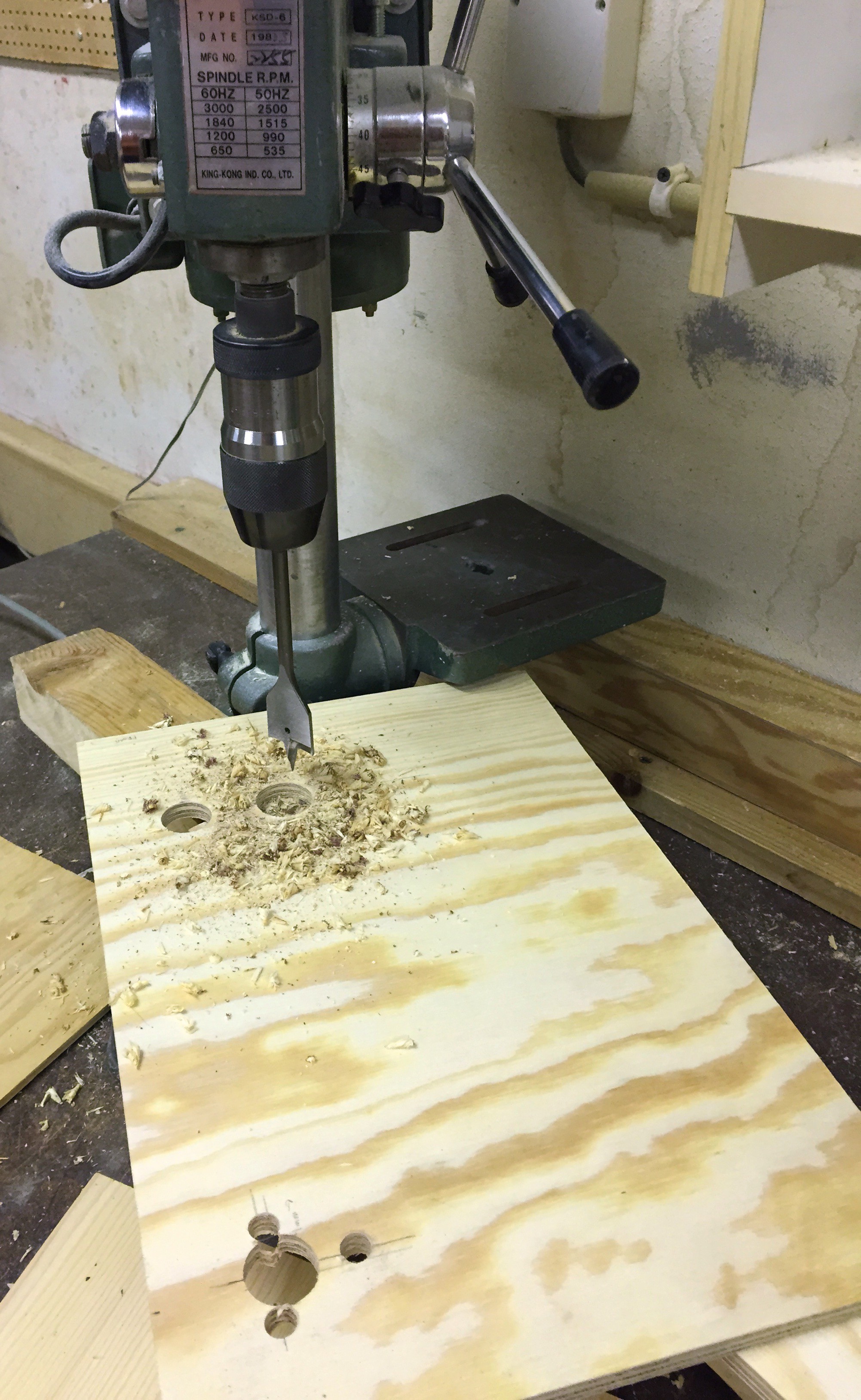
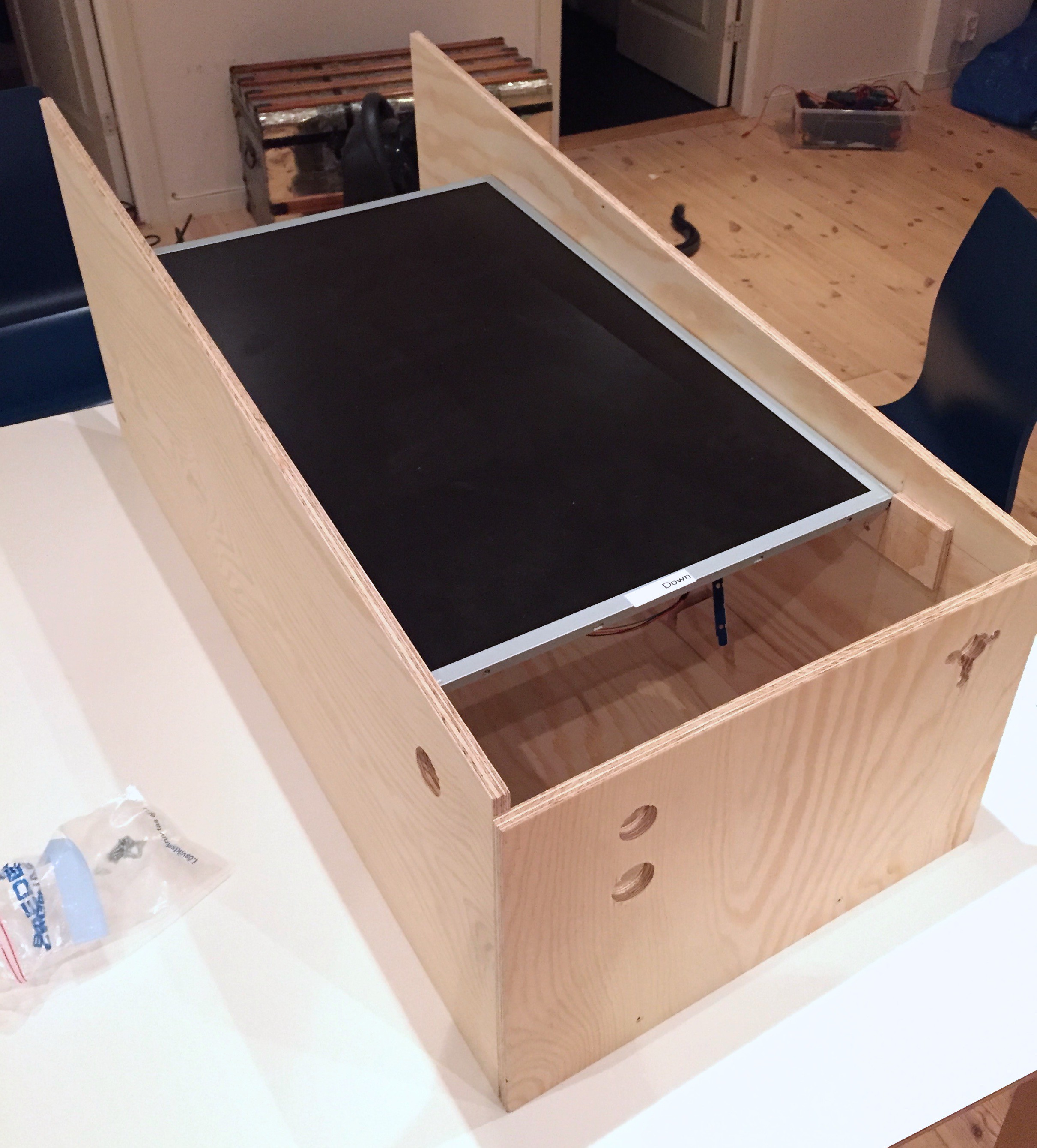
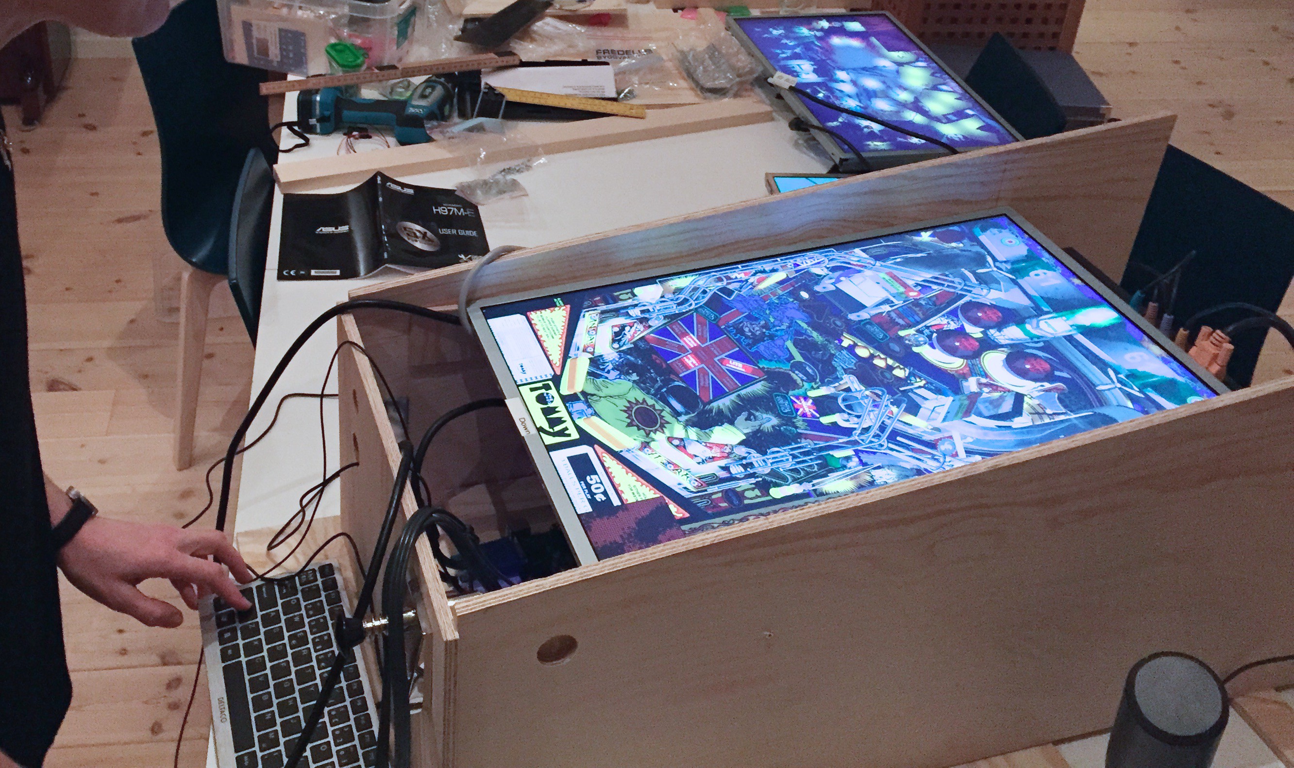
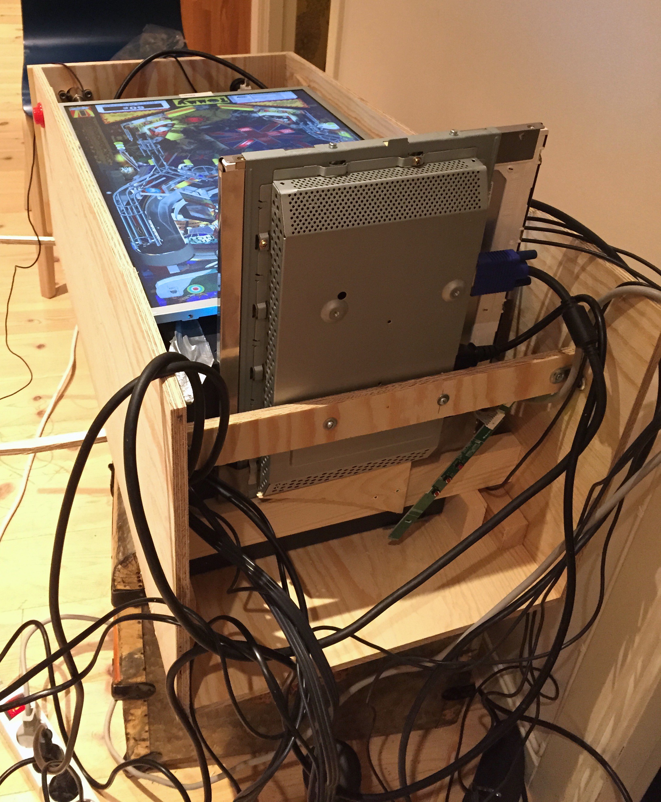
The first step was to see if I could find cheap used monitors. I got lucky, and bought one 23" and one 24" Dell IPS widescreen monitor for about €16 each. IPS monitors are good because they have good viewing angles. I ended up using the 24" monitor as playfield, exchanging the 23" monitor for the 20" IPS screen my desktop computer used, and using the 20" monitor for the back box.

5176461428419283594.jpg

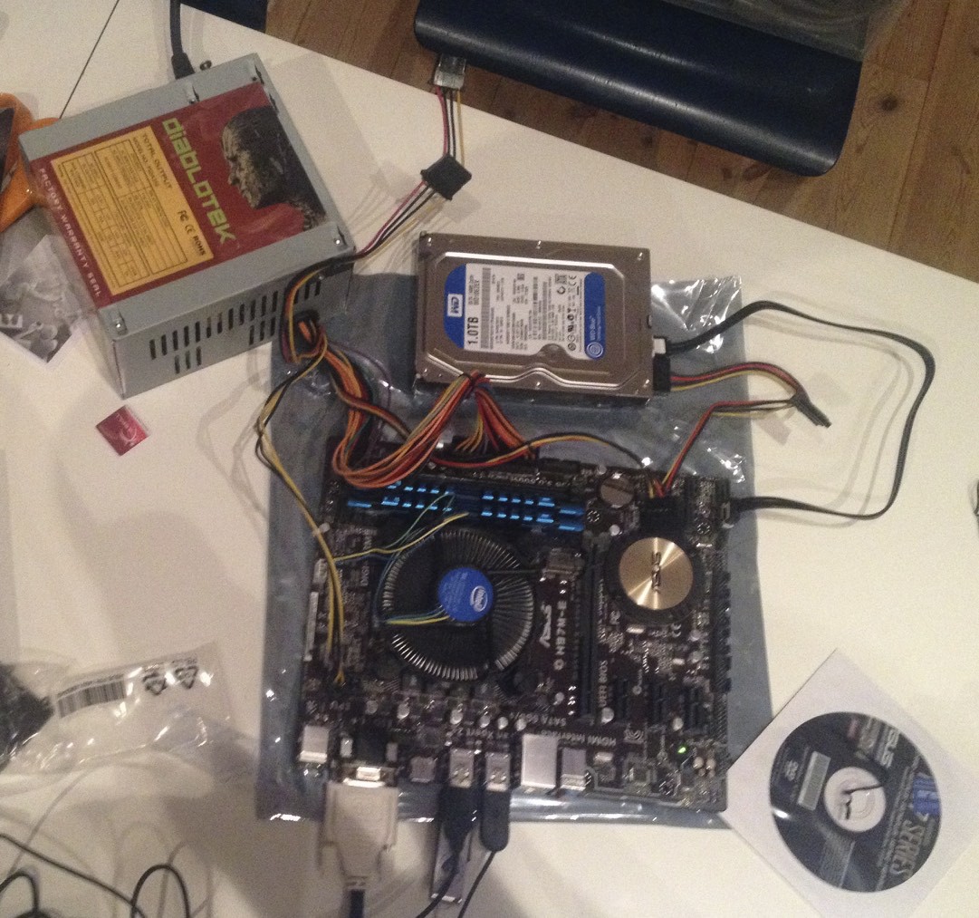
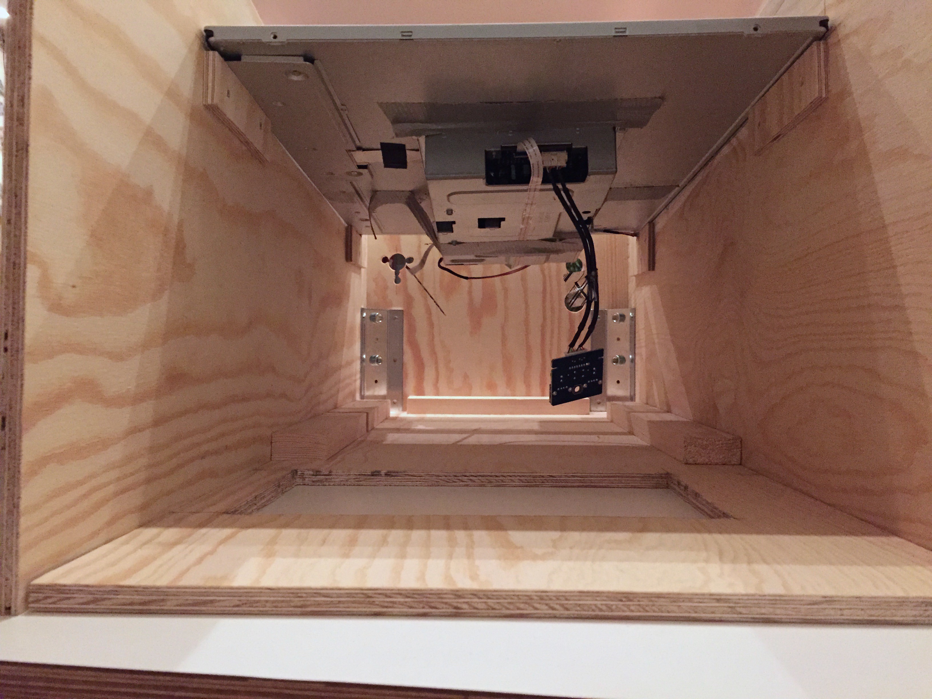
I also bought the single most expensive part of the project - the guts of a new computer. I chose an Asus H97M-E motherboard with an Intel i3 4150 3,5 GHz CPU, 8 GB of fast RAM, and a 1 TB WD Blue 10EZEX mechanical hard disk. I used a power supply I already had. Total cost: €348.

I wasn't sure if the Intel 4400 integrated graphics would be fast enough, but it works fairly well. If neccessary I'll add a discrete graphics card.

Also, I didn't think the motherboard / CPU would be able to drive three external monitors at the same time, but it turns out that it did.

3230141428419202689.jpg

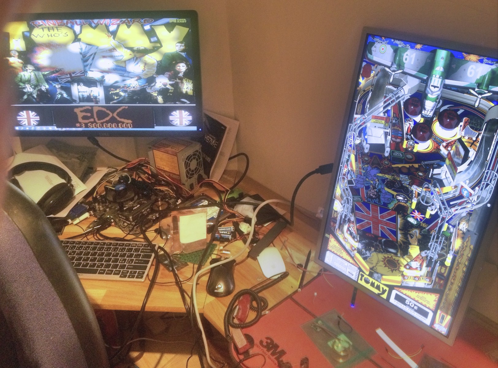
Up to this point, I had never run the Visual Pinball software, so I installed it to try it out. Unfortunately it only runs under Windows. Instead of paying hundreds of euros for Windows, I downloaded the free Windows 10 technical preview. My favorite pinball game, Tommy, worked fine, so I decided to go ahead with the rest of the project.


#2 pilotniq

pilotniq

    Hobbyist

  • Members
  • PipPip
  • 30 posts
  • Location:Stockholm, Sweden

  • Flag: Sweden

  • Favorite Pinball: Tommy

Posted 08 April 2015 - 10:00 PM

Planning, Speakers, CAD, Ventilation
Cross-posted from my Hackaday project page.

I spent countless hours in December 2014 making a CAD model of the cabinet in Sketchup.
In the Github repo you can find different versions of the Sketchup model:
981071428526612962.png
I realized that I had to buy the major components so that I could adapt the size of the cabinet to the major parts (monitors, subwoofer and speakers, mainly).

Speakers
The Visual Pinball and VPinMAME software is supposed to be able to separate the pinball table's music etc from the simulated sounds of the flippers and bumpers into separate speaker channels.
Therefore I got a 5.1 speaker system, with the intent of placing two satellite speakers in the front part of the cabinet to play the sound effects, two satellite speakers in the backbox, and a subwoofer in the middle of the cabinet.

Monitors
I 'decased' my monitors, taking the plastic frame and back off to make the cabinet as slim as possible.
Originally I had planned on using two monitors, but after learning that my motherboard could drive three monitors simultaneously, I decided to get a third small (15") monitor for the dot matrix display (DMD, which shows the scores among other things). I'll rotate it 90° and place it in the base cabinet behind the subwoofer (inspired by zany's build, see their video here which is much more fancy than my mounting).

CAD
I measured the monitors, speakers etc and made models ('components' in Sketchup terminology) for them.
The height of the cabinet was determined by the subwoofer, which is placed directly below the playfield screen.
I tried to get the proportions as similar as possible to a real pinball cabinet. The cabinet tilts about 3 degrees due to the legs being higher in the rear (they are mounter further down on the cabinet) than in the front, the angle of the playfield relative to the cabinet is about another three degrees, and the top part of the cabinet is another three degrees, summing to about 9 degrees from the horizontal.
The whole cabinet is about 40 cm wide by 80 cm deep.
I changed my mind about what thickness of plywood to use a couple of times, and Sketchup required lots of manual fiddling to adjust all the dimensions.

Ventilation
4524681428529100148.png
Many pinball cabinet builds seem to have large fans at the back of the cabinet. I will try to manage with out them.
My plan for the ventilation is to make holes at the bottom front of the cabinet, where cool air can enter. The air will be heated by the monitor and motherboard, and be drawn through the power supply, which is placed right in front of the subwoofer. I'll try to block of the center of the cabinet around the subwoofer and cabinet, so the air is forced through back through the PSU. Then it will rise behind the backbox screens, and exit and the top back of the cabinet, like a chimney. I'll make some holes for letting cool air in at the rear bottom of the cabinet too.


Edited: Fixed typo


Edited by pilotniq, 09 April 2015 - 07:16 PM.


#3 Peabo

Peabo

    Hobbyist

  • Members
  • PipPip
  • 28 posts
  • Location:RTP, NC

  • Flag: United States of America

  • Favorite Pinball: Cyclone, White Water

Posted 08 April 2015 - 10:14 PM

Nice work!  How do you plan to get to the interior?  Also, you'll want some kind of support for the graphics card when/if you add one.  The cabinet will get vibrated and the card slot won't put it with that for very long.  You may want to put a small, quiet fan at the base of the backbox to help move air up into the backbox.  I like the idea, it'll be interesting to see how much air moves through the cabinet.


#4 pilotniq

pilotniq

    Hobbyist

  • Members
  • PipPip
  • 30 posts
  • Location:Stockholm, Sweden

  • Flag: Sweden

  • Favorite Pinball: Tommy

Posted 08 April 2015 - 10:24 PM

Nice work!  How do you plan to get to the interior?  Also, you'll want some kind of support for the graphics card when/if you add one.  The cabinet will get vibrated and the card slot won't put it with that for very long.  You may want to put a small, quiet fan at the base of the backbox to help move air up into the backbox.  I like the idea, it'll be interesting to see how much air moves through the cabinet.


To get to the interior, I'll remove the bottom lockbar (I've made it out of oak), remove metal siderails, lift off the glass, remove some pieces of trim which are attached by magnets along the sides of the playfield to hide the bezel, and then lift out the playfield monitor. It sounds complex, but I rarely have to open it - I can reach most of the parts I've needed to fiddle (flipper button mechanisms, Arduino controller, USB cables) with from underneath the lockbar which is about 12 cm (4 inches) deep.


Thanks for the feedback about the graphics card jiggling. I hadn't thought about that. I'll keep it in mind if I do get a separate graphics card (but ir's working quite well with the integrated Intel 4400 graphics). 


I don't have a backside to the backbox yet. I've been running the game without any overheating problems. The temperature in the motherboard compartment was about 39 Celcius (102 F), and between the playfield monitor and the glass it was about 33 C (91 F).


#5 mviars

mviars

    Enthusiast

  • Members
  • PipPipPip
  • 115 posts
  • Location:Fort Myers, Florida

  • Flag: United States of America

  • Favorite Pinball: T2

  • PS3 Gamer Tag: mviars

Posted 09 April 2015 - 02:05 AM

Planning, Speakers, CAD, Ventilation
Cross-posted from my Hackaday project page.

I spent countless hours in December 2015 making a CAD model of the cabinet in Sketchup.
In the Github repo you can find different versions of the Sketchup model:


You went into the future just  to make your CAD??? hey if you go back "errr" forward again get me the next big Power Ball numbers in the US would ya!


Ha! Ha! Just having fun.


#6 pilotniq

pilotniq

    Hobbyist

  • Members
  • PipPip
  • 30 posts
  • Location:Stockholm, Sweden

  • Flag: Sweden

  • Favorite Pinball: Tommy

Posted 09 April 2015 - 07:16 PM


Planning, Speakers, CAD, Ventilation
Cross-posted from my Hackaday project page.

I spent countless hours in December 2015 making a CAD model of the cabinet in Sketchup.
In the Github repo you can find different versions of the Sketchup model:


You went into the future just  to make your CAD??? hey if you go back "errr" forward again get me the next big Power Ball numbers in the US would ya!


Ha! Ha! Just having fun.


Glad to see someone is reading my posts :-) Thanks for catching that, I'll fix it in the blog.


/Erland


#7 BigBoss

BigBoss

    Pinball Fan

  • VP Dev Team
  • PipPipPipPip
  • 749 posts

  • Flag: ---------

  • Favorite Pinball: Attack From Mars, Metallica, Theatre Of Magic, Shadow, Star Trek

Posted 10 April 2015 - 06:38 AM

yea. The Intel 4400 won't be sufficient to run everything smoothly. Close but not quite and definitely no AA. You'll need a better card such as a Gtx 750ti.

#8 tredog

tredog

    Hobbyist

  • Members
  • PipPip
  • 30 posts
  • Location:Indiana

  • Flag: United States of America

  • Favorite Pinball: Medieval Madness

Posted 10 April 2015 - 10:57 AM

Did you already go with full-sized legs?  I tried this originally and found it looked funny and was not very stable.  Ended up using much shorter legs from an old lunch table.  The mini-pin ended up a little shorter than I like but was plenty manageable.  I was thinking of adding a small platform to get it back to the right height, but not sacrifice stability or proportion. 


sig1.jpgsig3.jpg


#9 pilotniq

pilotniq

    Hobbyist

  • Members
  • PipPip
  • 30 posts
  • Location:Stockholm, Sweden

  • Flag: Sweden

  • Favorite Pinball: Tommy

Posted 10 April 2015 - 07:35 PM

yea. The Intel 4400 won't be sufficient to run everything smoothly. Close but not quite and definitely no AA. You'll need a better card such as a Gtx 750ti.

I have a friend that has an extra Radeon HD4850, so I can try that, do you think it would be enough?


But it has run fairly well. What tables need faster graphics card? I've run Tommy, Addams Family, Theatre of Magic, Twilght Zone and Indiana Jones. I think there's one place in Theatre of Magic that the ball stutters, but that's all I've noticed, I think.


Unfortunately the latest update of Windows 10 causes the newer versions of Visual Pinball to crash, so I've had to revert to 9.2.1 I think it is.


/Erland


#10 pilotniq

pilotniq

    Hobbyist

  • Members
  • PipPip
  • 30 posts
  • Location:Stockholm, Sweden

  • Flag: Sweden

  • Favorite Pinball: Tommy

Posted 10 April 2015 - 08:00 PM

Did you already go with full-sized legs?  I tried this originally and found it looked funny and was not very stable.  Ended up using much shorter legs from an old lunch table.  The mini-pin ended up a little shorter than I like but was plenty manageable.  I was thinking of adding a small platform to get it back to the right height, but not sacrifice stability or proportion.

 
Yes, I went with the longest legs I could find. I'm fairly tall (190 cm), so I didn't want my table too low. I think the cabinet looks good. It moves a bit more than a regular table I think when you hit it, probably because it's not as heavy. But it is fairly heavy (I think I calculated it should be around 20 kg. The subwoofer in particular adds weight. I have some rubber cups for the legs so the cabinet doesn't slide around on the floor.
 
Here's a picture (Sorry if it is too large, I can't figure out how to change the size):
 
6980721428695639502.jpg


#11 pilotniq

pilotniq

    Hobbyist

  • Members
  • PipPip
  • 30 posts
  • Location:Stockholm, Sweden

  • Flag: Sweden

  • Favorite Pinball: Tommy

Posted 01 May 2015 - 09:45 PM

Buying Plywood


There were several qualities and thicknesses of plywood available. Modifying the Sketchup model to adapt for changing plywood thickness was really error-prone and annoying.


Using the measurements from the Sketchup model, I calculated the area of the sides of the cabinet and backbox. It came out to 1.86 m² by treating the sides as rectangles.


Finally I settled for a fair grade of pine plywood, 10 mm thick, 2m x 1 m for 498 kr (€53) at Fredells.


I used Inkscape to make a plan for how to fit the various pieces onto the plywood, and how to have the lumberyard cut the sheet (red lines) with as few cuts as possible (they charged for each cut, I ended up paying 100 kr (€11) for the cuts:

7732991430513131126.png

Unfortunately it turned out that the lumberyard could only cut all the way across the sheet, so I had to do some quick improvisations.


Finally, I had my pieces:

6980411430513474536.jpg


#12 pilotniq

pilotniq

    Hobbyist

  • Members
  • PipPip
  • 30 posts
  • Location:Stockholm, Sweden

  • Flag: Sweden

  • Favorite Pinball: Tommy

Posted 01 May 2015 - 10:30 PM

Building the Main Box


Sorry about some of the big images, and the black backgrounds. I had a hard time trying to resize them with the forum editor. Read this post on Hackaday to get better formatting.


I built the base cabinet first, and left the backbox for later.

6852281430514360977.jpg


The first part of building the cabinet was sawing the sides to shape (with my favorite tool, the Japan saw;


Next, drilling holes for the buttons and plunger:

6911971430514185973.jpg

2724121430514428027.jpg

I then screwed on some smaller wood pieces so that I could screw the front and sides onto the base.


In retrospect I think maybe I should have used iron angles screwed on the inside instead of screwing through the front and sides pieces. This way I would not have had to use filler (spackel) over the screws on the sides, an dI could maybe disassemble the box later without destroying the paint on the sides.
9722201430515037736.jpg

492231430514625497.jpgI made the hole in the base for the subwoofer by drilling out parts and then sawing it out. I was a bit afraid that the cabinet would be weakened by the big subwoofer hole (and the subwoofer is one of the heaviest components of the cabinet). But that turned out not to be a problem.

8987681430515122176.jpgChecking the fit:

5976371430515188148.jpg[I screwed some small pieces onto the sides to support the playfield monitor.

The corners are held by the leg brackets. The back brackets are turned upside down so that the front legs are attached higher on the cabinet than the rear legs. This makes them shorter, and the entire cabinet tilted a bit towards the player.

I glued in triangular wooden pieces behind the leg brackets to make it easier to drill the holes for the leg bolts later. They are not visible in these photos.
2034481430515574912.jpgI hoped that I had calculated the dimensions properly, and I had!
1529201430515922259.jpgThis is what the cabinet looked like from the back:

6283461430515961585.jpgI had to give it the first test run in the cabinet:

4837011430516097544.jpgThis assembly only took two to three days - I had the pieces home on January 17, and did the first test on January 19.


It really felt like the project was moving along quickly now, especially after spending a month planning, doing Sketchup work and buying second hand components.


#13 pilotniq

pilotniq

    Hobbyist

  • Members
  • PipPip
  • 30 posts
  • Location:Stockholm, Sweden

  • Flag: Sweden

  • Favorite Pinball: Tommy

Posted 03 May 2015 - 07:57 PM

Mounting the Computer & DMD monitor

January 23, 2015

I mounted my motherboard directly on the plywood bottom, and the hard drive next to it.

In the picture below the plunger is at the bottom left, the two front satellite speakers are the black pieces to the right next to it. The hard drive is above the lower satellite speaker. The big black box at the right is the subwoofer. To the top left of the subwoofer is the PSU. It is placed high up so that the fan drives the hot air back behind the subwoofer.

4104921430679431394.jpg

Here's a side view:

9249431430679683839.jpg

The wooden crossbar serves as a support for the playfield monitor electronics box, which did not stay attached to the monitor itself after I decased it. It also supports the distance sensor aimed at the plunger.

The 15" DMD monitor was installed in portrait orientation behind the subwoofer. Lots of cables!

8376331430680133861.jpg


Electronics

I bought a small Arduino clone, a Pololu A-Star 32U4 Micro, to handle the button presses, sense the plunger movements and read the accellerometer that will sense the cabinet being pushed. It was 99 SEK (€ 11).

It will appear to the computer as a USB keyboard and joystick.

2234181430680513452.jpg

To sense the plunger positions, I bought a Sharp GP2Y0A41SK0F IR distance sensor for 105 SEK (€ 11). It has an analog output.

I got an ADXL345 accelerometer from E-bay for €5.12. It uses SPI. It needs resistor dividers to level shift the 5V of the microcontroller to the 3.3V of the accelerometer.

I used the built-in pull-up resistors of the 32u4 chip for the switches, so I tied one pole of all the buttons (start, exit, right flipper, left flipper) to ground, and the other to an microcontroller pin.

The plunger distance and accelerometer signals are presented to the PC as joystick inputs on axes Z and X and Y respectively. In order to do this I used a very useful Arduino HID project.

The IR sensor signal is quite noisy, but with some software filtering I think I have gotten it to work reasonably well.

The source code is in my GitHub repository.

I mounted the various components on a stripboard. The green board is the microcontroller, and the blue board is the accelerometer. The buttons are connected to the screw terminals. Some of the voltage divider resistors are underneath the accelerometer board.

6992491430682730996.jpg


This ended up being quite an inexpensive solution. There are commercial solutions, such as the VirtuaPin™ Digital Plunger Kit v2, but it is $160 which is much more expensive than my solution.

In the future, an idea I have is to control the volume by connecting a rotary encoder to the microcontroller, and have the microcontroller send volume up and volume down media control keys to the PC. This way the volume should be controllable in the same way regardless of whether the headphone output or speakers are used.


#14 paymaster

paymaster

    Enthusiast

  • Members
  • PipPipPip
  • 59 posts

  • Flag: United States of America

  • Favorite Pinball: The Addams Family

Posted 04 May 2015 - 11:53 PM

yea. The Intel 4400 won't be sufficient to run everything smoothly. Close but not quite and definitely no AA. You'll need a better card such as a Gtx 750ti.


DDH69 confirmed in another thread that Intel 4400 is working well.  

http://www.vpforums....showtopic=30534


I am running Intel 4600 in my cab - it works great.


#15 pilotniq

pilotniq

    Hobbyist

  • Members
  • PipPip
  • 30 posts
  • Location:Stockholm, Sweden

  • Flag: Sweden

  • Favorite Pinball: Tommy

Posted 05 May 2015 - 08:20 PM

I'm currently running the older 9.2.1 version of Visual Pinball, because the latest 9.9.1 crashes. When it does run, the older 9.2.1 runs smoother than the newer version on the integrated graphics.


  • The Lockdown Bar

    February 13, 2015

    Real pinball cabinets have a metal bar across the top of the front of the pinball cabinet, where players rest their hands. It is also the keystone piece  to open the cabinet, the coin door is opened to release the lockdown bar, which then allows the removal of the glass, and opening the play field:

    1540271430764076153.jpg

    A regular lockdown bar wouldn't fit my cabinet, since it is smaller than a standard pinball cabinet. I didn't have access to metalworking tools, so I made my own lockdown bar out of some oak boards.

    I took one board, and used a router to make slots where the glass and side rails would be:

    9576151430764475651.jpg

    I then glued some scrap plywood pieces to match the inside corners of the cabinet:

    2125181430764597948.jpg

    Finally, I glued some oak strips to the side of the board to make it seem twice as thick, and then sanded down the edges to round them:

    2563371430764730322.jpg

    It fits really nice and tight to the cabinet. I had intended to have magnets hold it in place, but I don't feel that I need to now.


#16 pilotniq

pilotniq

    Hobbyist

  • Members
  • PipPip
  • 30 posts
  • Location:Stockholm, Sweden

  • Flag: Sweden

  • Favorite Pinball: Tommy

Posted 06 May 2015 - 09:36 PM

My pinball cabinet was featured by Hackaday!


http://hackaday.com/...eighbors-happy/


Also tagged with one or more of these keywords: minicab, 24