MadMax's Future Pinball Table Detail Design Guide
…or “How to Create Realistic Pinball Tables”
Initial release, 12th September 2006
The HTML version of this guide can be found at this
URL:
http://www.futurepinball.com/forum/viewtopic.php?t=1862
Anyone can build a pinball table with Future Pinball.
It’s very easy to get something together that looks convincing because FP has
very realistic graphics and objects to work with. However, there are some
guidelines to follow if you want to build a table with truly realistic visuals,
and I’m taking you through them in this guide.
For starters, you should have some basic idea of what you
want to create since this guide is not for absolute beginners. But if you have
a table in the works and want to spice it up with some realistic detail, read
on.
1. The Beginning: The Real World
When designing a pinball table on the computer, the
best comparison you could have is a real pinball machine. Practically all of
the little tricks I’m about to show you bring your Future Pinball table closer
to a real machine since you will be recreating details which are common on
them, but often overlooked in FP. So if you have access to a pinball machine or
you can find detailed photos of one, you can always compare your work to the
real thing. A good photo resource is, of course, the Internet Pinball Database
at http://www.ipdb.org.
Future Pinball is a simulator and as such its essence
is detail and realism. The program provides enough models and functions to
build a truly realistic pinball table, but it isn’t always obvious how these
functions should be used. It starts with the placement of screws and ends with
custom-tailored details, like realistic ramps. A little creativity can even
substitute some missing features in FP, and some things I came up with will be
shown in this guide.
I have created a customized “new table” which has many
of the features implemented that I describe here. You can use the table for
research or to build your own creation. Since it’s basically an empty table
with some added stuff to quicker get you started, I won’t mind if you mess around
with it and use it as a base to build your own. Of course you can remove the
credits in the info, I just put them there so you know where this table came
from. ;-) The table can be downloaded here:
http://www.silverball-magic.com/FP/CustomNewTable_MadMax.zip
2. The Groundwork: Building a Solid Fundament
Once you have a table layout in mind, start with the
basics that make this layout work. That means, don’t go around placing plastics
and screws yet until you’ve created a playable and working layout of metal wall
guides, bumpers, target banks and ramps. But how can we add some realism to the
table when we are just in the first stage of construction?
Ball Trough:
The ball trough on FP’s default “new table” has a huge
unrealistic flaw – the exit to the plunger lane goes straight upwards from
inside the trough, kicking the ball up high into the lane and forcing the
player to wait a second for the ball to come down and rest on the plunger. This
is not only annoying on many otherwise fine tables, but it’s also not how a
real machine’s trough works. A real ball trough has a bend on the inside walls
which direct the ball so that it is kicked straight onto the outer wall of the
plunger lane, bouncing back and falling down instantly. The ball comes to rest
on the plunger within milliseconds and is ready to play.
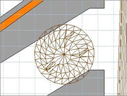
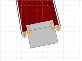
The modification to make to the ball trough is simple:
add a non-smooth shape point on
either trough wall and move the points close to the exit, then shape a bend
with them to force the ball horizontally out of the trough. See the picture for
reference.
You may get a better or worse ball serve depending on
how close you make the walls around the trough kicker and how far the kicker is
away from the exit. The default strength
of 3 should be enough to get the ball out quickly.
Plunger Lane:
 Normally a plunger lane has a
metal protector on the right wall to prevent damage to the wall from served
balls. When shaping a short plunger lane with a diagonal exit, the whole wall
would be covered with a metal wall guide that would lead to the exit.
Normally a plunger lane has a
metal protector on the right wall to prevent damage to the wall from served
balls. When shaping a short plunger lane with a diagonal exit, the whole wall
would be covered with a metal wall guide that would lead to the exit.
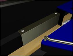
To build a protector like on a real machine, simply
create a metal wall guide with a
length of roughly 11 centimeters,
position it on the right wall, make a surface
of equal length that covers the guide and the wall and put it on top. You can
add Orn-Screw models to the surface
to simulate that the protector was screwed into the wall. Sphere map both the guide and the surface to make it look like
metal.
Flippers:
By default, the flippers are strangely shifted a little
upwards and don’t line up with the lane guides. Moving both flippers down by one millimeter (one tap on the down
arrow key) positions them perfectly.
Also, flipper strength and animation is a little
critical in the current release of FP. On normal strength, the flippers are
strong enough to get the ball up on high ramps even with a table slope of 8
degrees (which in fact are not 8 true degrees!), and increasing the
strength makes the flippers extremely strong, only useful for widebody tables
or high table slopes. However, it also makes the flipper movement more
realistic since they will appear to “snap” up quicker like on real machines,
and on very high strength settings there is even a slight improvement in ball
physics (center shots are easier and the ball takes better paths). It’s up to
you to figure out what suits your table best, but keep in mind that high
flipper strength can lead to uncontrolled air balls and malfunctioning ramps.
Rubbers:
When shaping a rubber around posts, try to make it as
smooth and hugging as possible. The rubber shouldn’t loosely sit on the posts,
but in fact be tightly strapped around them. Use the blue circle on posts in the editor view as a reference. The circle
represents the carving of a post where the rubber should sit in, so fitting the
rubber closely around the circle with at least three smooth shape points and one non-smooth ending point on each
side should give you a nice result. Also, rubbers never bow on a side; they
should be straight on every side of the shape they represent.
The default rubber offset
for star posts is 14, and 20 for the second rubber on double-carved posts.
Metal posts usually use an offset of 14 as well.
Posts:
 One thing that Future Pinball
lacks is a Z-axis view, so you are forced to know the height of posts, rubbers,
guides and plastics in order to get it all together. When it comes to posts,
there are some differences in height
that should be watched:
One thing that Future Pinball
lacks is a Z-axis view, so you are forced to know the height of posts, rubbers,
guides and plastics in order to get it all together. When it comes to posts,
there are some differences in height
that should be watched:
star posts: 27 mm
rubber bumper posts: 29 mm
smooth plastic posts: various
In general there is one thing that is often overlooked
by designers. Star posts need to be affixed to the playfield with a long screw
on pinball machines, and this screw is also the holder for plastics which are
placed on top of the posts. There is an ornament model called Orn-Nut-Spacer which represents exactly
this post screw, and it should go into the center of every (translucent) star
post so it actually looks as if they were fixed to the playfield! But more
importantly, the nut on the screw (the spacer) which holds the post in place
adds a height of 2 millimeters to the
post, totaling in 29 millimeters just
like the metal wall guides and rubber bumper posts. If you place your plastics
on star posts later, you should always keep this in mind as you might want to
make sure that your plastic offset is
29 millimeters on every post/guide, be it a star post or not. And to get these
height compatible, you can use the spacer nut.
Metal Wall Guides:
These guides shape any lanes, loops or blockades on
your table. Aside from careful shaping there is one thing to watch out for if
you want to stay real: whenever two wall guides meet, put a post between them. The post acts as a
screw point for the plastic that will be put over the guides, and it will
smoothen out the otherwise sharp edge that would appear on meeting guides.
Adding a post to the end of a wall guide can also be useful if you put a ramp
next to it or if you want to add something like a target bank, which needs
posts on both sides.
Target Banks:
A standup (leaf)
target bank only needs a rubber
bumper post at each end of the bank to separate it from the rest of the
table. Also, since the bank will most likely be covered with a plastic later,
the posts act as screw points for the plastic.
A drop target bank
should have a single or double rubber
behind it to let the ball bounce back in case it hits a target which is already
down. The rubber should fully cover the length of the bank and be attached to
two star posts. A rubber bumper post at each end of the bank will keep the
outer drop targets from being hit from the sides, unless you want that to
happen. You can screw a plastic to these posts later to cover the bank just
like with standup targets.
Colours & Texturing:
Correctly colouring a pinball table can make a
difference between realism and oddity. I’ve seen some tables with true blue,
100% red and light green ramps, walls and plastics, and they looked like a
child’s toy. Decent colours make a
table realistic. But colouring in FP has an important effect on models and
textures as well.
For example, it’s never a good idea to work with
absolute values. If you want to make some-thing black, setting the RGB values to 0 is not a good idea since
it will ruin the 3D effect of the object – top and side will look identical and
will be hard to distinguish, but slightly upping the RGB values to 30 (very
dark gray) will give you a nice black object with a slight bright-ness
difference on the sides. Similarly, pure white should be used carefully as it
often makes objects look “glowing”. A very light shade of gray, like the one in
the custom colour table, is almost
perfectly white on most models and doesn’t have the glow effect.
When applying a texture to an object, the colour will
be layered over it and determine the tone of the texture. Using different
shades of gray you can determine how bright you want the texture to be. This is
especially important when using sphere
maps: a darker sphere map can be made brighter with white colouring while a
bright map can be toned down using dark gray.
 An example: you want to
texture a spinner bracket with a sphere map. Normally the “chrome silver” map produces a rather dark and golden tone which
doesn’t look particularly polished. There are two alternatives: either you use
the “chrome white” map which is
essentially brighter, but looks a little dull because light reflections are
smoother. However, you could also keep using the silver map and change the
colour of the model to white, enhancing the brightness
of the map and reducing the gold.
An example: you want to
texture a spinner bracket with a sphere map. Normally the “chrome silver” map produces a rather dark and golden tone which
doesn’t look particularly polished. There are two alternatives: either you use
the “chrome white” map which is
essentially brighter, but looks a little dull because light reflections are
smoother. However, you could also keep using the silver map and change the
colour of the model to white, enhancing the brightness
of the map and reducing the gold.
Overall I’m using these textures and colours for the
following objects:
metal wall guides: chrome white, light gray (default)
wire guides, wire ramps, metal posts: chrome silver,
white
rubbers: light black (RGB 30, 30, 30), light gray
(custom colour table)
GI bulbs: bright olive (RGB 213, 213, 181)
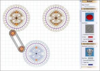
bumpers: full colour for lit cap, balanced darker tone
for unlit cap, deep dark colour for skirt
plastics: dark or mixed colours
Lights & Flashers:
GI bulbs are a little tricky to set up.
First, don’t forget the ornament holes
under them and send them to the back. Make sure that any objects you want to
block the light are drawn in front of
the bulb, but that flasher bulbs should be drawn in front of everything to really flash over the table objects, creating
an “overbright” light effect. For white bulbs, the best and probably most
realistic colour is bright olive (RGB 213, 213, 181) since GI bulbs are rarely
pure white. Also, while the colour tone may seem a little dark, Future Pinball
will make it very bright in-game since bulbs have a radiosity and intensity
that will increase the brightness and make the colour “glow” a little. A nice radius for most bulbs is 64 millimeters although you might want
to up that a little depending on how much scattered light you want in an area.
 For “naked flasher bulbs”,
i.e. flashers without a plastic dome, there’s a neat trick. Simply insert a
normal bulb, make it completely white
and set the radius very high, like 96 millimeters. The white colour and
radius will make this bulb extremely bright. Don’t forget to draw this bulb in front of any object as
you would do it with flashers, so the bright flash will overdraw any objects.
Then flash this bulb using the Flash-ForMs
script function, and it will appear a lot like a plain white flasher bulb
without a dome. To further enhance the effect, position a real flasher close to the bulb, set its
colour to plain white, and disable the
model to make the flasher invisible. Using the FlashForMs script function, flash the flasher with identical para-meters
parallel to the flasher bulb you created earlier. The bulb will now provide the
visual flashing effect while the invisible flasher will light up the whole
playfield and screen, like a dome flasher would if you were using that. You now
have a perfect naked flasher!
For “naked flasher bulbs”,
i.e. flashers without a plastic dome, there’s a neat trick. Simply insert a
normal bulb, make it completely white
and set the radius very high, like 96 millimeters. The white colour and
radius will make this bulb extremely bright. Don’t forget to draw this bulb in front of any object as
you would do it with flashers, so the bright flash will overdraw any objects.
Then flash this bulb using the Flash-ForMs
script function, and it will appear a lot like a plain white flasher bulb
without a dome. To further enhance the effect, position a real flasher close to the bulb, set its
colour to plain white, and disable the
model to make the flasher invisible. Using the FlashForMs script function, flash the flasher with identical para-meters
parallel to the flasher bulb you created earlier. The bulb will now provide the
visual flashing effect while the invisible flasher will light up the whole
playfield and screen, like a dome flasher would if you were using that. You now
have a perfect naked flasher!
3. The Topping: Adding Detail
With a nice foundation to build on, you can now
concentrate on details that will make your table look more realistic on the
surface.
Plastics & Screws:
 One thing to know about
plastics is that they are usually not
translucent. They let light shine through and produce shadows of posts and
objects touching them, but you can’t see the playfield below a plastic unless
it’s clear (no artwork printed on it). Many people think they should make their
plastics translucent to get the GI lamps to shine through, but the “reverse drawing” approach gives much
more solid results. For one, you will get a definite light halo on top of your
plastic graphics that nicely brightens them up, similar to the light dots on
the backglass. Secondly, your graphics will remain fully coloured when the
plastic is opaque. It’s very easy to produce opaque plastics with light halos
over them: draw your plastic above the GI bulbs, then send the plastic to the back and turn on ordered halo glow for the bulbs. The halos will now be drawn on top
of the plastic since it’s rendered behind them, and any graphic on it will get
nice light spots as if the plastic was lit from below.
One thing to know about
plastics is that they are usually not
translucent. They let light shine through and produce shadows of posts and
objects touching them, but you can’t see the playfield below a plastic unless
it’s clear (no artwork printed on it). Many people think they should make their
plastics translucent to get the GI lamps to shine through, but the “reverse drawing” approach gives much
more solid results. For one, you will get a definite light halo on top of your
plastic graphics that nicely brightens them up, similar to the light dots on
the backglass. Secondly, your graphics will remain fully coloured when the
plastic is opaque. It’s very easy to produce opaque plastics with light halos
over them: draw your plastic above the GI bulbs, then send the plastic to the back and turn on ordered halo glow for the bulbs. The halos will now be drawn on top
of the plastic since it’s rendered behind them, and any graphic on it will get
nice light spots as if the plastic was lit from below.
 When creating a plastic, be
sure to go the same route you went with rubbers: often more shape points produce smoother rounded
corners, and plastics should always be rounded on their outline, never have a
sharp edge on any end. Ideally, the plastic should follow the shape of the
rubber beneath it if there is one. Make sure that posts under the plastic are
centered and that the plastic is not shifted to a side. Plastics on posts
should always start at the height of
the posts, often 29 millimeters. If
you work with star posts, use the Orn-Nut-Spacer
model where possible to get the post height up to 29 mm, then put the plastic
over it and finish up with a nut model
on top. This will create the perfect illusion that the post is fixed to the
playfield with a spacer nut and that the plastic is tightly screwed to the
post. If for some reason you can’t use spacer nuts on star posts, or if you put
your plastic on top of rubber bumper posts, add Orn-Screw models to the plastic to “screw” it onto the posts under
it. Don’t forget the screw/nut texture!
When creating a plastic, be
sure to go the same route you went with rubbers: often more shape points produce smoother rounded
corners, and plastics should always be rounded on their outline, never have a
sharp edge on any end. Ideally, the plastic should follow the shape of the
rubber beneath it if there is one. Make sure that posts under the plastic are
centered and that the plastic is not shifted to a side. Plastics on posts
should always start at the height of
the posts, often 29 millimeters. If
you work with star posts, use the Orn-Nut-Spacer
model where possible to get the post height up to 29 mm, then put the plastic
over it and finish up with a nut model
on top. This will create the perfect illusion that the post is fixed to the
playfield with a spacer nut and that the plastic is tightly screwed to the
post. If for some reason you can’t use spacer nuts on star posts, or if you put
your plastic on top of rubber bumper posts, add Orn-Screw models to the plastic to “screw” it onto the posts under
it. Don’t forget the screw/nut texture!
If you line up plastics along metal wall guides, it often helps to let a little rim stand over
the wall so the plastic fully closes up with it. Make sure your wall guide is
high enough to meet the plastic (default 29 millimeters) and keep in mind that
the default height of the outer playfield
walls is 32 mm. Any plastic you attach to them must have a height of 32 mm and can’t properly meet
with wall guides or posts unless you change the height of the playfield wall. I
ran for a compromise of 30 mm on both the playfield wall and the guides so I
could safely attach the plastic to both, and any posts under it would have a
space of a millimeter which is hardly visible.
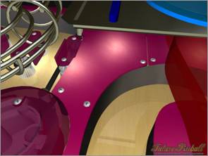
Applying screws is not only important on posts. For
example, plastics are often screwed into the metal wall guides when there are
no posts to screw them to. Simply adding a screw near the wall guide will do
the trick. Of course you can also add rubber bumper posts anywhere and screw
your plastics to them. This can be useful if the plastic can be looked under,
i.e. if the trick with the screw near the wall guide doesn’t work.
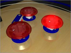
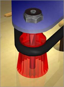
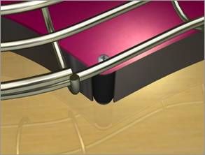
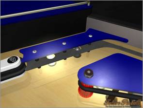
Models like bumpers
and bumper lane guides look much more
realistic with screws on them. For bumpers, place two screws inside the two openings of the bumper base (see picture)
and offset them by 43 millimeters. It
will look as if the bumper cap was screwed to the base. Do the same for lane
guides, placing the guide on two posts (offset
10 mm for thin posts, 8 mm for star posts without spacer nuts) followed by two screws to fix the guide to the posts.
The screws get an offset of 29/31 mm
since the guide is 2 mm thick.
A final detail to add to screws and nuts is random rotation. On a real machine,
naturally not all screws will be rotated to zero degrees, so giving your screws
some random rotation values will make them seem “screwed in”.
Gates & Brackets:
 When using a gate, a bracket should be added to hold it.
Brackets and gates look best with the “chrome
silver” sphere map and a colour of 100% white. The gate must be attached to
a surface to get the correct height,
otherwise it will sit inside the playfield. Attaching the gate to the wall next
to it will give it the right height at most times since this wall will probably
be used to attach the bracket as well. Gate brackets are not symmetrical; they have a longer and a shorter screw side and
the longer side is 2 millimeters lower! You cannot place a gate bracket
When using a gate, a bracket should be added to hold it.
Brackets and gates look best with the “chrome
silver” sphere map and a colour of 100% white. The gate must be attached to
a surface to get the correct height,
otherwise it will sit inside the playfield. Attaching the gate to the wall next
to it will give it the right height at most times since this wall will probably
be used to attach the bracket as well. Gate brackets are not symmetrical; they have a longer and a shorter screw side and
the longer side is 2 millimeters lower! You cannot place a gate bracket 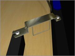 on top of two identically high
walls or posts; one of them must be 2 mm higher than the other. A gate bracket
is only 1 mm thick, so add two screws with an offset of 1 mm to the walls or offset them by 28/30 mm when placing
the bracket on posts. This is also a perfect example of when not to use
the spacer nut on a star post: if you
want to have the bracket’s lower end on the post, simply place it directly on
it and put the screw on top, 28 mm high. Since star posts are only 27 mm high
and you’ll want to get the higher end of the bracket to 29 mm, a star post
without a spacer nut is perfect for the lower end. It’s done like this on real
machines too.
on top of two identically high
walls or posts; one of them must be 2 mm higher than the other. A gate bracket
is only 1 mm thick, so add two screws with an offset of 1 mm to the walls or offset them by 28/30 mm when placing
the bracket on posts. This is also a perfect example of when not to use
the spacer nut on a star post: if you
want to have the bracket’s lower end on the post, simply place it directly on
it and put the screw on top, 28 mm high. Since star posts are only 27 mm high
and you’ll want to get the higher end of the bracket to 29 mm, a star post
without a spacer nut is perfect for the lower end. It’s done like this on real
machines too.
A spinner bracket
has the same height on both ends, so when using a spinner bracket, nothing of
the above is required.
Flipper Lane Guides:
On FP’s default table, the flipper lane guides have no plastics. This would work for early electronics
tables, but all modern pinball machines have plastics on the lane guides, often
one, sometimes two layers. It’s very simple to create plastics for the lane
guides: simply copy the existing metal guides and move the copies up to 27 millimeters. Then increase the height of the lane guide holders so that they touch the plastics and offset the
screws by 29 mm. To make the left plastic more like on a real machine, cut down
the upper left end so that it is on about a line with the upper right end of the
right plastic.
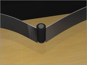
Flipper lane guides often have GI bulbs under and openings in them to let the light shine through.
Creating such an opening is a little work since it requires you to add shape
points inside of the metal. Start with two
points on the upper or lower side of the metal and try to position them so
that they meet on a straight line. Basically the sideline of the metal should
look as if there was no shape point on it at all. Once aligned, use these two
points to cut out a circular hole in
the metal, adding smooth shape points
and forming a ring. See the picture for reference. Then place the GI bulb and
ornament hole under the opening. Send the lane guide plastic to the back (or
the bulb to the front) to get the light halo on top of it.
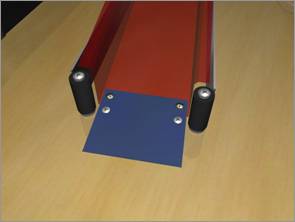
Ramps:
 Creating ramps is easy with
FP. Making them look real requires a little creative work. In its current
version FP lacks ramp entrance blades.
It’s easy to create such a blade, though: make your ramp, then create another
ramp (model T2) without walls (set the
wall height to 0). Make its width a little smaller than your real
ramp’s width and set the end height to 2
or 3 millimeters. Make this flat ramp short so that it almost shapes a
square. Apply the “plastic black” sphere
map and move the square slightly above
the entrance of your real ramp. This is your ramp entrance blade.
Creating ramps is easy with
FP. Making them look real requires a little creative work. In its current
version FP lacks ramp entrance blades.
It’s easy to create such a blade, though: make your ramp, then create another
ramp (model T2) without walls (set the
wall height to 0). Make its width a little smaller than your real
ramp’s width and set the end height to 2
or 3 millimeters. Make this flat ramp short so that it almost shapes a
square. Apply the “plastic black” sphere
map and move the square slightly above
the entrance of your real ramp. This is your ramp entrance blade.
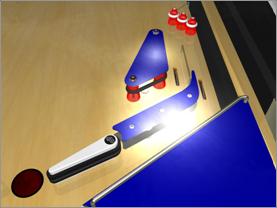
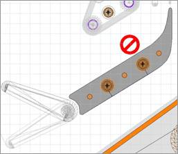
To attach the blade to the ramp and the playfield, add four screws as shown on the picture. Offset them so that they appear
correctly on the blade. On a real ramp, the blade is attached with two rivets
that can currently only be simulated by screws. To make the screws look more
like rivets, sphere mapping them is a
good idea. Normally texture the “real” screws that fix the blade to the
playfield.
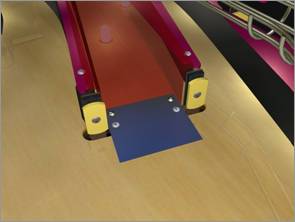
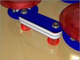
To make the entrance even more realistic, you can add two rubber bumper posts in front of the
ramp walls. This will ensure that the ball bounces off if it misses the ramp
entrance a little, and it will also prevent the ball from accidentally rolling
under the ramp. Usually you should also use guides or some other form of
blockade around the ramp so the ball won’t get stuck under it.
If the posts are not your style and you want to make
the most use of your playfield space, you can also work with two slim standup (leaf) targets. Put
each target in front of a ramp wall, then rotate them so they line up. Don’t
forget to add round or hammer ornament
holes for the targets. If the holes are too large, you can hide a part of
them under the entrance blade!
Sound:
Sound effects in FP lack a little realism. They are not
bad, but there are better sounds out there. One thing that sounds like it
should are the flippers. Their sound is very close to the real thing and
shouldn’t be changed, but the file
that FP uses has a latency which can
be seen on any stronger flipper strength. I have edited the file and cut out
the latency, and the flippers sound much snappier now. The file is included in
my sample table.
Also, slingshots and bumpers could use better sound
effects. While the slings are okay, just not as snappy as they should be, the
bumpers on real machines either have a much harder click/thump than in FP, or
they feature a plastic sound that kind of “oomphs” a bit. There are some fine
bumper sounds in several mechanical sound
libraries, and these libraries were made with a purpose. Use them and get
your sounds real!
4. Conclusion
If you have tried some of the ideas in this guide, you
have seen how easy it is to add realism to your tables. Of course many details
mean a big polygon count, but since everyone has the option to turn off
ornaments and render objects with less polygons, it shouldn’t pose a big problem.
Future Pinball runs great on many systems today and some added detail shouldn’t
be a performance problem. Enhance your tables!